
User Manual
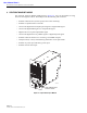


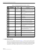


Table Of Contents

ADCP-75-124 • Issue B • April 2002 • Section 2: Description
Page 2-14
©
2002,
ADC
Telecommunications,
Inc.
The
attenuator
can
be
set
in
1
dB
increments.
The
attenuator
is
software
controlled
and
is
adjusted
through
the
NOC/NEM
interface
or
the
EMS
software
GUI.
4.6 Optical Connection
Fiber
optic
connections
between
the
STM
and
the
HU
are
supported
through
either
two
(non-
diversity
unit)
or
three
(diversity
unit)
SC-type
optical
connector
ports.
On
non-diversity
units,
one
port
is
used
for
connecting
the
forward
path
optical
signal
and
the
other
port
is
used
for
connecting
the
primary
reverse
path
optical
signal.
On
diversity
units,
a
third
optical
port
is
used
for
connecting
the
diversity
reverse
path
optical
signal.
4.7 Service Interface Connection
The
service
interface
connection
between
the
STM
and
a
local
laptop
computer
loaded
with
the
EMS
software
is
supported
by
a
single
DB-9
female
connector.
The
service
interface
connector
provides
an
RS-232
DTE
interface.
The
STM
service
interface
connector
supports
local
communications
with
both
the
STM
and
the
corresponding
HU.
4.8 Powering
The
STM
is
powered
by
120
or
240
Vac
(50
or
60
Hz)
power
which
is
supplied
through
a
three-
conductor
AC
power
cord.
The
power
cord
is
provided
with
the
RU
cabinet.
One
end
of
the
cord
is
hard-wired
to
the
AC
power
outlet
box
and
the
other
end
is
terminated
with
a
molded-on
plug
cap.
The
power
cord
connects
to
a
3-wire
AC
cord
connector
mounted
on
the
STM
front
panel.
A
switch
on
the
STM
front
panel
provides
AC
power
On/Off
control.
The
STM
(and
the
connected
LPA)
may
be
powered
by
a
24
Vdc
back-up
battery
system
which
is
available
as
an
accessory
kit.
A
connector
is
provided
on
the
STM
front
panel
for
connecting
the
wiring
harness
for
the
back-up
battery
system.
4.9 Cooling
Continuous
air-flow
for
cooling
is
provided
by
a
single
fan
mounted
on
the
rear
side
of
the
STM
housing.
An
alarm
is
provided
that
indicates
if
a
high
temperature
condition
(>50º
C/122º
F)
occurs.
If
the
temperature
falls
below
32º
F
(0º
C),
the
fan
automatically
shuts
off.
The
fan
may
be
field
replaced
if
it
fails.
4.10 User Interface
The
STM
user
interface
consists
of
the
various
connectors,
switches,
and
LEDs
that
are
provided
on
the
STM
front
panel.
The
STM
user
interface
points
are
indicated
in
Figure 2-6
and
described
in
Table 2-3.