
User Manual


ADCP-75-158 • Preliminary Issue A • June 2003 • Section 3: Host Unit Installation
Page 3-5
© 2003, ADC Telecommunications, Inc.
2. Remove both mounting brackets from the mounting shelf (requires Phillips screwdriver)
and save screws for reuse.
3. Locate the extra mounting brackets that are provided with the mounting shelf and select
the brackets that correspond to the rack type. Each mounting shelf includes extra brackets
for installing the mounting shelf in the following rack types:
• 19-inch EIA
• 19-inch WECO
• 23-inch EIA
• 23-inch WECO
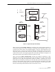
4. Install the replacement mounting brackets as shown in Figure 3-3. Use the screws
removed in step 2 to attach the new brackets to the mounting shelf.
Figure 3-3. Installing the Replacement Mounting Brackets
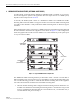
5. Position the mounting shelf in the designated mounting space in the rack (per system
design plan) and then secure the mounting brackets to the rack using the four #12-24
machine screws provided as shown in Figure 3-4.
6. Install each host module in the mounting shelf (see Figure 3-4). A rail on the side of the
module fits into a guide within the mounting.
7. Secure each host module to the mounting shelf by twisting the handle on each quarter-turn
fastener 90º.
8. Carefully store the pigtail leads from each host module. The routing and connection
procedures for the pigtails are provided in Section 7.
16885-A