
User Manual


ADCP-75-158 • Preliminary Issue A • June 2003 • Section 2: Description
Page 2-31
© 2003, ADC Telecommunications, Inc.
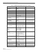
DC power connector Screw-type terminal strip
RF coaxial cable connectors N-type (female)
Service connector DB-9 (female) RS-232 DTE interface
CAN connectors RJ-45 jack
Power input ± 24 or ± 48 VDC ± 21 to ± 60 VDC
Power consumption 55 watts
Current rating 1 Amp at –48 VDC
Reliability at 25ºC MTBF 80,000 hours Excluding fans
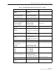
Physical/Environmental/
Electrical - Remote Unit Outdoor
Cabinet
Cabinet dimensions (H×W×D) 25.6 × 10.13 × 20.75 inches
(674 × 257 × 527 mm)
Mounting Wall, pole, or pedestal Pedestal mounting requires ped-
estal mount kit. (accessory)
Weight 80 lbs (36.3 kg) Includes modules
Weather resistance NEMA-3R, removable dust filter
Operating temperature –30º to 50º C (–22º to 122º F)
Storage temperature –40º to 70º C (–40º to 158ºF)
Humidity 10% to 90% No condensation
External alarm connector Screw-type terminals External alarm inputs
AC power connection 3/4- or 1/2-inch conduit Per local code or practice.
Antenna cable connector N-type female
Fiber optic cable size
0.375 to 0.875 inch (10 to 22
mm) diameter cable
9/125, single-mode
Lightning protection 20 kA IEC 1000-4-5 8/20 µs
waveform
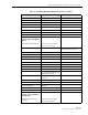
Service connector DB-9 female (on STM) RS-232 DTE interface
Power input 120 or 240 VAC, 50 or 60 Hz
Power consumption 360 Watts
Current rating 5 Amps maximum at 120 VAC
Reliability at 25ºC MTBF 50,000 hours Excluding fans and air filter
Physical/Environmental/
Electrical - Remote Unit Indoor
Mounting Shelf
Mounting Shelf dimensions
(H×W×D)
14.15 × 17.39 × 15.6 inches
(359 × 442 × 396 mm)
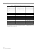
Table 2-6. 1900 MHz 20 Watt System Nominal Specifications, continued
PARAMETER SPECIFICATION REMARKS