
User Manual


ADCP-75-158 • Preliminary Issue A • June 2003 • Section 3: Host Unit Installation
Page 3-2
© 2003, ADC Telecommunications, Inc.
• Phillips screwdriver (#2)
• TORX screwdriver (T20 bit)
• Pliers
• Wire cutters
• Wire stripper
• Tool kit for attaching N-type male connectors to coaxial cable
• Multimeter
• Optical power meter
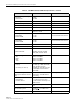
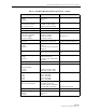
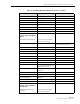
The following materials are required to complete the procedures in this section:
• #18 AWG (1.0 mm) insulated stranded copper wire (for chassis grounding wire)
• #18 AWG (1.0 mm) red and black insulated copper wire (for DC power wires)
• Category 3 or 5 cable (for external alarm system wires)
• #6 ring terminal (1) for #18 wire (for chassis ground wire connection)
• #6 fork terminals (2) for #18 wire (for DC power wiring connection)
• Single-mode patch cord(s) with SC connectors (1, 2 or 3 depending on the application)
• High performance, flexible, low-loss 50-ohm coaxial cable
• N-type male connectors
• Wire ties
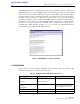
1.2 Unpacking and Inspection
This section provides instructions for opening the shipping boxes, verifying that all parts have
been received, and verifying that no shipping damage has occurred. Use the following
procedure to unpack and inspect the HU and any accessories:
1. Open the shipping cartons and carefully unpack each component from the protective
packing material.
2. Check each component for broken or missing parts. If there are damages, contact ADC
(see section 6 at the end of this manual) for an RMA (Return Material Authorization) and
to reorder if replacement is required.
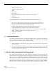
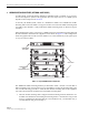
2 FIBER OPTIC CABLE ROUTING AND INSTALLATION GUIDELINES
The outside plant (OSP) fiber optic cables should be routed between the HU and RU and
terminated before the equipment is installed. A diagram of a typical fiber optic cable routing is
shown in Figure 3-1. At the HU, the OSP cable should be terminated at a fiber distribution panel
and spliced to pigtails. Patch cords may then be used to link the HU optical ports to the OSP
cable terminations. Whenever possible, a guideway such as the FiberGuide system should be
provided to protect the fiber optic patch cords from damage and to prevent excessive bending.
The procedures for connecting the OSP cable optical fibers to the HU is provided in Section 7.