
User's Manual


ADCP-75-158 • Issue 1 • July 2003 • Section 5: Maintenance
Page 5-7
© 2003, ADC Telecommunications, Inc.
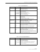
LED: HOST UNIT Color: Red Alarm Type: Major
PROBLEM: A major alarm fault detected by HU.
POSSIBLE CAUSE CORRECTIVE ACTION/COMMENTS
1. Fiber optic link fault.
2. HU and STM band mismatch.
3. The HU has failed.
1. Follow procedure specified when the PORT 1/
PORT 2 LED is red.
2. Replace HU or STM with correct unit.
3. Replace the HU.
LED: REMOTE UNIT Color: Yellow Alarm Type: Minor
PROBLEM: A minor alarm fault is detected at the RU.
POSSIBLE CAUSE CORRECTIVE ACTION/COMMENTS
1. The STM or LPA is overheating. 1. Check RU LED indicators and refer to Table 5-8
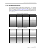
LED: REMOTE UNIT Color: Red Alarm Type: Major
PROBLEM: A major alarm fault is detected at the RU.
POSSIBLE CAUSE CORRECTIVE ACTION/COMMENTS
1. Fiber optic link fault.
2. AC power failure at RU.
3. High VSWR.
4. The RU cabinet door is open or the STM or
LPA has failed.
1. Check RU LED indicators and refer to Table 5-8.
2. Check RU LED indicators and refer to Table 5-8.
3. Check RU LED indicators and refer to Table 5-8.
4. Check RU LED indicators and refer to Table 5-8.
LED: DRIVE Color: Yellow Alarm Type: Minor
PROBLEM: The RF input signal level is below the underdrive threshold.
POSSIBLE CAUSE CORRECTIVE ACTION/COMMENTS
1. Faulty BTS or faulty coaxial connection
between the HU and the BTS.
2. Incorrect attenuation in forward path RF coax-
ial link.
1. Check forward path signal level at the HU.
2. Check Host Forward Attenuator setting and
adjust if attenuation is too high.
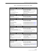
LED: DRIVE Color: Red Alarm Type: None
PROBLEM: The RF signal is above the overdrive threshold.
POSSIBLE CAUSE CORRECTIVE ACTION/COMMENTS
1. Composite output signal level from BTS is too
high.
2. Incorrect attenuation in forward path RF
coaxial link.
1. Check BTS composite output signal level and
adjust if too high.
2. Check Forward Attenuator setting and adjust if
attenuation is too low.
LED: PORT 1/PORT 2 Color: Red Alarm Type: Major
PROBLEM: Excessive errors are detected in the reverse or forward path optical signal or no forward or reverse
path optical signal is detected.
POSSIBLE CAUSE CORRECTIVE ACTION/COMMENTS
1. Faulty reverse or forward path optical fiber.
2. Faulty optical transmit port at the STM or
HU; or faulty optical receive port at the STM
or HU.
1. Test optical fiber. Clean connector if dirty. Repair
or replace optical fiber if faulty. (See Section 4.1).
2. Test optical ports. Replace HU or STM if port is
faulty (See Section 4.2).
Table 5-7. Host Unit Fault Isolation and Troubleshooting, continued