
User's Manual


ADCP-75-158 • Issue 1 • July 2003 • Section 4: Operation
Page 4-7
© 2003, ADC Telecommunications, Inc.
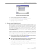
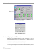
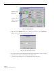
Figure 4-4. Select Control Program File Window
4. Select the first file to download and click on the OK button.
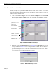
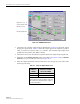
5. Click on the HOST Load button (see Figure 4-3) to start the download.
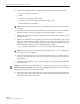
6. Repeat steps 4 and 5 for each file that requires downloading.
7. Repeat steps 2 through 5 for the REMOTE.
2.3 Determine Forward Path Input Signal Level
The level of the composite RF input signal at the FORWARD RF IN port at the HU will vary
depending on the type of BTS, the cable loss, the number of channels present, and the required
forward path composite power. If maximum composite RF output is required, the signal level of
the composite forward path RF signal at the HU forward path input must be adjusted to fall
within a range of –9 to –40 dBm. If the signal level is not within this range, it must be adjusted
to fall within this range through the use of an external attenuator capable of handling the BTS
forward path output power.
If using the Conditioning Panel or Duplexing Panel, refer to the Digivance 800 and 1900 MHz
Interface Panels User Manual (ADCP-75-147) for the procedures for measuring and adjusting
the input RF signal level at the HU. If connecting a single HU to a single BTS, use the following
procedure to measure and adjust the input RF signal level at the HU:
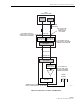
1. Connect a spectrum analyzer or power meter to the forward path output port of the BTS.
The required signal levels and test points are shown in Figure 4-5.
2. If using a spectrum analyzer, proceed to step 3. If using a power meter, measure the
composite signal power from the BTS and then proceed to step 5.
3. Measure the RF level of a single carrier, such as the control channel, in dBm. Make sure
the resolution bandwidth of the spectrum analyzer is 30 kHz. Maximum power in any
channel should not exceed 5W (+37 dB).
Note: Check the input rating of the test equipment and the output rating of the BTS. To
avoid burning out the spectrum analyzer or power meter, it may be necessary to insert a
30 dB 100W (or similar) attenuator between the BTS and test equipment.