
User's Manual


ADCP-75-158 • Issue 1 • July 2003 • Section 4: Operation
Page 4-13
© 2003, ADC Telecommunications, Inc.
4. Place the RF ON/OFF switch on the LPA in the ON position.
5. If using a spectrum analyzer, proceed to step 6. If using a power meter, measure the
composite signal power from the STM and then proceed to step 8.
6. Measure the RF level of a single carrier, such as the control channel, in dBm. Make sure
the resolution bandwidth of the spectrum analyzer is 30 kHz.
7. Calculate the total composite signal power using the following formula:
P
tot
= P
c
+ 10Log N – (see Note)
Where,
P
tot
is the total composite power in dBm
P
c
is the power per carrier in dBm as measured in step 6, and
N is the total number of channels.
8. Record the result measured in step 5 or calculated in step 7.
9. Place the MUTE/NORM/RESET switch on the LPA in the OFF position.
10. Disconnect the spectrum analyzer or RF power meter from the STM ANTENNA port.
11. Re-connect the antenna cable to the STM ANTENNA port.
2.7 Enter Remote Forward Attenuation
The STM internal forward path attenuator setting is used to reduce the power level of the
composite output signal level at the STM antenna port. The maximum composite output signal
level at the STM antenna port is set using the Host internal forward attenuator (see Section 2.4).
However, component variations may result in the output power at the STM antenna port being
slightly above or below the required power per channel. If this is the case, the STM forward
attenuator may be used in conjunction with the Host forward attenuator to add or remove
attenuation to produce the required output signal level. If less power is required, the STM
forward attenuator may be used to reduce the power level. The default setting is 0 dB. Use the
following procedure to change the STM forward attenuation:
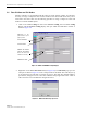
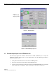
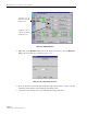
1. Click on the REMOTE LPA tab. The REMOTE LPA display will open within the EMS
main window as shown in Figure 4-10.
Note: If calculating the composite power for a CDMA system, reduce the initial result by
16.23 dB.
Note: To comply with Maximum Permissible Exposure (MPE) requirements, the
maximum composite output from the antenna cannot exceed 1000 Watts EIRP and the
antenna must be permanently installed in a fixed location that provides at least 6 meters
(20 feet) of separation from all persons.