
User's Manual


ADCP-75-158 • Issue 1 • July 2003 • Section 4: Operation
Page 4-15
© 2003, ADC Telecommunications, Inc.
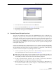
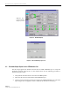
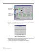
Figure 4-11. Remote Fwd Att Pop-Up Screen
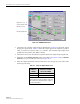
6. Verify that the appropriate RF output signal level appears in the RF Pwr-VSWR Low
section (see Figure 4-10). This is primarily a reference value and should not take the place
of external test equipment when determining the power level of the composite RF output
signal. Depending on the modulation type and number of channels, the EMS software may
report a power level that is higher or lower than the actual RF output signal.
2.8 Enter Host Reverse Attenuation
The level of the RF signal that should be input to the BTS will vary depending on the type of
BTS, the receive distribution, and the number of channels present. To interface with the BTS,
the reverse path signal level must be adjusted to provide the signal level required by the BTS.
The HU provides from –1 dB of gain to +30 dB of gain in the reverse path. Use the following
procedure to set the reverse path gain:
1. Check the BTS manufacturer’s specifications to determine the composite signal level
required at the BTS reverse path input port.
2. Determine the overall gain and loss imposed on the signal by the antenna, antenna cable,
and by the cables that connect the HU to the BTS.
3. Determine the amount of gain required to raise the reverse path signal to the level required
at the BTS.
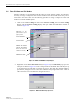
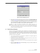
4. Click on the HOST RF tab. The HOST RF display will open within the EMS main
window as shown in Figure 4-12.
Note: To comply with Maximum Permissible Exposure (MPE) requirements, the
maximum composite output from the antenna cannot exceed 1000 Watts EIRP and the
antenna must be permanently installed in a fixed location that provides at least 6 meters
(20 feet) of separation from all persons.