
User Manual

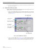

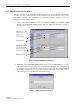
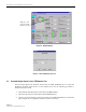
Table Of Contents
- SECTION 1: Overview
- SECTION 2: Description
- SECTION 3: Host Unit Installation
- SECTION 4: Operation
- SECTION 5: Maintenance
- SECTION 6: General Information
- ABOUT THIS MANUAL
- RELATED PUBLICATIONS
- ADMONISHMENTS
- GENERAL SAFETY PRECAUTIONS
- STANDARDS CERTIFICATION
- LIST OF ACRONYMS AND ABBREVIATIONS
- SECTION 1: Overview
- SECTION 2: Description
- SECTION 3: Host Unit Installation
- 1 before starting installation
- 2 OSP Fiber Cable Installation Guidelines
- 3 WDM mounting procedure (optional accessory)
- 4 HU mounting procedure
- 5 Chassis ground connection
- 6 coaxial cable connections
- 7 optical connections
- 8 controller area network connections
- 9 service interface connection
- 10 external alarm system connections
- 11 dc power connections
- SECTION 4: Operation
- 1 before starting operation
- 2 turn-up system and verify operation
- 2.1 Turn-Up Procedure
- 2.2 Download HU and RU System Software
- 2.3 Determine Forward Path Input Signal Level
- 2.4 Enter Site Name and Site Number
- 2.5 Enter Host Forward Attenuation
- 2.6 Determine Output Signal Level at STM Antenna Port
- 2.7 Enter Remote Forward Attenuation
- 2.8 Enter Host Reverse Attenuation
- 2.9 Enter Host Forward and Reverse Delay
- SECTION 5: Maintenance
- SECTION 6: General Information
ADCP-75-126 • Issue B • April 2002 • Section 4: Operation
Page 4-3
©
2002,
ADC
Telecommunications,
Inc.
2.1 Turn-Up Procedure
Use
the
following
procedure
to
turn-up
the
system:
1. Temporarily
disconnect
the
external
alarm
system
or
notify
the
alarm
system
provider
that
testing
is
in
progress.
2. If
turning-up
multiple
HU
and
RU
systems
that
have
not
been
configured
for
operation
before,
temporarily
disconnect
the
CAN
cables
from
the
NET
IN
and
NET
OUT
ports
of
each
HU.
3. Determine
if
the
forward
path
composite
input
signal
level
at
the
Host
Unit
FORWARD
RF
IN
port
is
between
–10
and
–40
dBm
and
adjust
level
by
installing
an
external
attenuator
if
required.
Refer
to
Section
2.3
for
the
calculation
and
adjustment
procedure.
4. Connect
the
EMS
computer
(if
not
already
connected)
to
the
SERVICE
connector
on
the
HU
or
STM
front
panel.
If
necessary,
a
separate
laptop
computer
loaded
with
the
EMS
software
can
be
temporarily
connected
and
used
to
initially
configure
the
system.
5. Place
the
ON/OFF
switch
on
the
HU
in
the
ON
position
(press
I).
6. Place
the
ON/OFF
switch
on
the
STM
in
the
ON
position
(press
I).
7. Wait
6
to
8
seconds
for
the
HU
and
the
RU
modules
to
initialize
and
then
observe
the
LED
indicators
on
the
HU,
STM
and
LPA.
Refer
to
Section
5
for
the
troubleshooting
procedures
if
the
indicators
do
not
respond
as
specified.
8. Start
up
the
Digivance
EMS
software
program.
The
EMS
main
window
will
open
as
shown
in
Figure 4-1.
Note:
The
EMS
software
should
be
installed
on
a
PC-type
computer
and
the
PC’s
COM
port
should
be
configured
to
interface
with
the
HU.
For
information
about
installing
the
EMS
software
and
configuring
the
PC’s
COM
port,
refer
to
the
Digivance
Element
Management
System
Software
User
Manual
(ADCP-75-125).
Note:
By
default,
all
HU’s
and
RU’s
are
programmed
with
the
same
site
number
and
name.
This
can
cause
problems
for
the
Digivance
EMS
if
multiple
HU’s
with
the
same
site
number
and
site
name
are
networked
together
through
the
CAN
interface.
It
is
therefore
advisable
to
temporarily
disconnect
the
CAN
interface
cables
from
the
HU
until
a
unique
site
number
and
name
can
be
entered
for
each
HU
and
its
corresponding
RU.
HOST UNIT SPECTRUM TRANSPORT MODULE LINEAR POWER AMPLIFIER
POWER
–
Green
AC
POWER
–
Green FAIL
–
Off
STANDBY
–
Off STANDBY
–
Off
SHUTDOWN
–
Red
HOST
UNIT
–
Green HOST
UNIT
–
Green
Digital
Display
–
FORCED
SHUTDOWN
REMOTE
UNIT
–
Green
STM
–
Green
DRIVE
–
Green,
Yellow,
or
Red PA
–
Green
PORT
1/PORT
2
–
Green VSWR
–
Green
PORT
3
–
Green
(diversity
unit
only)
PORT
1/PORT
2
–
Green
PORT
3
–
Green
(diversity
unit
only)
FCC ID: F8I-DVLRCSPCS - User Manual - Part 4