
User Manual
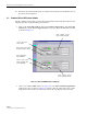
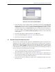

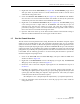
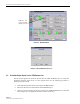


Table Of Contents
- SECTION 1: Overview
- SECTION 2: Description
- SECTION 3: Host Unit Installation
- SECTION 4: Operation
- SECTION 5: Maintenance
- SECTION 6: General Information
- ABOUT THIS MANUAL
- RELATED PUBLICATIONS
- ADMONISHMENTS
- GENERAL SAFETY PRECAUTIONS
- STANDARDS CERTIFICATION
- LIST OF ACRONYMS AND ABBREVIATIONS
- SECTION 1: Overview
- SECTION 2: Description
- SECTION 3: Host Unit Installation
- 1 before starting installation
- 2 OSP Fiber Cable Installation Guidelines
- 3 WDM mounting procedure (optional accessory)
- 4 HU mounting procedure
- 5 Chassis ground connection
- 6 coaxial cable connections
- 7 optical connections
- 8 controller area network connections
- 9 service interface connection
- 10 external alarm system connections
- 11 dc power connections
- SECTION 4: Operation
- 1 before starting operation
- 2 turn-up system and verify operation
- 2.1 Turn-Up Procedure
- 2.2 Download HU and RU System Software
- 2.3 Determine Forward Path Input Signal Level
- 2.4 Enter Site Name and Site Number
- 2.5 Enter Host Forward Attenuation
- 2.6 Determine Output Signal Level at STM Antenna Port
- 2.7 Enter Remote Forward Attenuation
- 2.8 Enter Host Reverse Attenuation
- 2.9 Enter Host Forward and Reverse Delay
- SECTION 5: Maintenance
- SECTION 6: General Information

ADCP-75-126 • Issue B • April 2002 • Section 4: Operation
Page 4-14
©
2002,
ADC
Telecommunications,
Inc.
Figure 4-10. REMOTE LPA Display
2. Check
the
level
of
the
RF
output
signal
(as
determined
in
Section
2.6)
against
the
system
design
plan
specifications.
Table 4-1
shows
the
output
signal
level
required
to
provide
5
watts
per
channel
for
systems
with
1
to
4
channels.
The
maximum
output
signal
level
permitted
for
the
system
is
43.5
dBm
(22.4
watts).
3. Determine
if
more
or
less
attenuation
is
required
to
produce
the
required
output
signal
level.
4. Right-click
on
the
Remote
Fwd
Att
section
of
the
display
(see
Figure 4-10).
The
Remote
Fwd
Att
pop-up
screen
will
open
as
shown
in
Figure 4-11.
5. Enter
the
required
attenuation
value
and
click
OK
to
close
the
pop-up
screen
and
to
make
the
changes
take
effect.
Table 4-1. Composite Output Signal Levels
NUMBER OF
CHANNELS
OUTPUT SIGNAL LEVEL
REQUIRED TO PROVIDE 5
WATTS PER CHANNEL
137
dBm
240
dBm
342
dBm
443
dBm
When
there
are
five
or
more
channels,
each
channel
will
always
be
less
than
5
watts
since
the
system
has
a
maximum
power
output
of
22.4
watts
(43.5
dBm).
Right-click here to
open the Remote Fwd
Att pop-up screen
RF output signal level