
User Manual

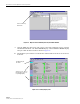
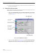
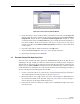

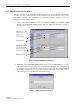
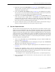
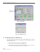
Table Of Contents
- SECTION 1: Overview
- SECTION 2: Description
- SECTION 3: Host Unit Installation
- SECTION 4: Operation
- SECTION 5: Maintenance
- SECTION 6: General Information
- ABOUT THIS MANUAL
- RELATED PUBLICATIONS
- ADMONISHMENTS
- GENERAL SAFETY PRECAUTIONS
- STANDARDS CERTIFICATION
- LIST OF ACRONYMS AND ABBREVIATIONS
- SECTION 1: Overview
- SECTION 2: Description
- SECTION 3: Host Unit Installation
- 1 before starting installation
- 2 OSP Fiber Cable Installation Guidelines
- 3 WDM mounting procedure (optional accessory)
- 4 HU mounting procedure
- 5 Chassis ground connection
- 6 coaxial cable connections
- 7 optical connections
- 8 controller area network connections
- 9 service interface connection
- 10 external alarm system connections
- 11 dc power connections
- SECTION 4: Operation
- 1 before starting operation
- 2 turn-up system and verify operation
- 2.1 Turn-Up Procedure
- 2.2 Download HU and RU System Software
- 2.3 Determine Forward Path Input Signal Level
- 2.4 Enter Site Name and Site Number
- 2.5 Enter Host Forward Attenuation
- 2.6 Determine Output Signal Level at STM Antenna Port
- 2.7 Enter Remote Forward Attenuation
- 2.8 Enter Host Reverse Attenuation
- 2.9 Enter Host Forward and Reverse Delay
- SECTION 5: Maintenance
- SECTION 6: General Information

ADCP-75-126 • Issue B • April 2002 • Section 4: Operation
Page 4-4
©
2002,
ADC
Telecommunications,
Inc.
Figure 4-1. Digivance Element Management System Main Window
9. Open
the
View
drop
down
menu
and
connect
to
the
Host
and
Remote
pair
by
selecting
“NotNamed/NotNamed”.
The
HOST
Alarms
display
and
the
REMOTE
Alarms
display
will
open
within
the
main
window
as
shown
in
Figure 4-2.
10. Download
the
system
software
to
both
the
Host
and
the
Remote
unit.
Refer
to
Section
2.2
for
details.
Figure 4-2. Selecting Display Tabs
Click to view drop
down menu
Clicking on the tabs in
this list will open the cor-
responding display.
Host/Remote pair
site name