
User Manual

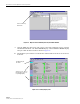
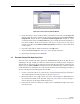

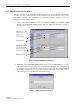
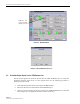
Table Of Contents
- SECTION 1: Overview
- SECTION 2: Description
- SECTION 3: Host Unit Installation
- SECTION 4: Operation
- SECTION 5: Maintenance
- SECTION 6: General Information
- ABOUT THIS MANUAL
- RELATED PUBLICATIONS
- ADMONISHMENTS
- GENERAL SAFETY PRECAUTIONS
- STANDARDS CERTIFICATION
- LIST OF ACRONYMS AND ABBREVIATIONS
- SECTION 1: Overview
- SECTION 2: Description
- SECTION 3: Host Unit Installation
- 1 before starting installation
- 2 OSP Fiber Cable Installation Guidelines
- 3 WDM mounting procedure (optional accessory)
- 4 HU mounting procedure
- 5 Chassis ground connection
- 6 coaxial cable connections
- 7 optical connections
- 8 controller area network connections
- 9 service interface connection
- 10 external alarm system connections
- 11 dc power connections
- SECTION 4: Operation
- 1 before starting operation
- 2 turn-up system and verify operation
- 2.1 Turn-Up Procedure
- 2.2 Download HU and RU System Software
- 2.3 Determine Forward Path Input Signal Level
- 2.4 Enter Site Name and Site Number
- 2.5 Enter Host Forward Attenuation
- 2.6 Determine Output Signal Level at STM Antenna Port
- 2.7 Enter Remote Forward Attenuation
- 2.8 Enter Host Reverse Attenuation
- 2.9 Enter Host Forward and Reverse Delay
- SECTION 5: Maintenance
- SECTION 6: General Information

ADCP-75-126 • Issue B • April 2002 • Section 4: Operation
Page 4-5
©
2002,
ADC
Telecommunications,
Inc.
11. Click
on
the
HOST
Config
tab
and
on
the
REMOTE
Config
tab
(see
Figure 4-2).
The
HOST
Config
display
and
the
REMOTE
Config
display
will
open
within
the
main
window.
12. Enter
the
Site
Name
and
Site
Number
for
both
the
HOST
and
the
REMOTE
unit.
Refer
to
Section
2.4
for
details.
13. Reconnect
the
CAN
cables
to
the
HU’s
NET
IN
and
NET
OUT
ports.
14. Verify
that
no
Major
(except
Major
Extern
Alarm)
or
Minor
alarms
are
being
reported
in
either
the
HOST
or
REMOTE
Alarm
displays
and
that
all
alarm
fields
(except
Major
Extern
Alarm)
are
green.
15. Click
on
the
HOST
RF
tab
(see
Figure 4-2).
The
HOST
RF
display
will
open
within
the
main
window.
16. Enter
the
Host
Fwd
Att
(Forward
Attenuation)
values.
This
sets
the
forward
input
RF
signal
level
at
the
HU.
Refer
to
Section
2.5
for
details.
By
default,
this
value
is
set
to
0
dB.
If
the
DRIVE
LED
on
the
HU
front
panel
was
red,
it
should
turn
green
when
this
step
is
completed.
17. Determine
if
the
RF
output
power
at
the
STM
ANTENNA
is
at
the
correct
level
per
channel
up
to
a
composite
maximum
of
43.5
dBm.
Refer
to
Section
2.6
for
details.
18. Click
on
the
REMOTE
LPA
tab
(see
Figure 4-2).
The
REMOTE
PA
display
will
open
within
the
main
window.
19. Enter
the
Remote
Fwd
Att
value.
This
adjusts
the
RF
output
signal
level
at
the
STM
ANTENNA
port.
Refer
to
Section
2.7
for
details.
By
default
this
value
is
set
to
0
dB.
20. Place
the
RF
ON/OFF
switch
(on
LPA
front
panel)
in
the
ON
position.
21. Verify
that
the
SHUTDOWN
LED
indicator
(on
LPA
front
panel)
turns
from
red
to
off
and
the
Digital
Display
message
changes
from
FORCED
SHUTDOWN
to
NORMAL
OPERATION.
22. Click
on
the
HOST
RF
tab
(see
Figure 4-2).
The
HOST
RF
display
will
open
within
the
main
window.
23. Enter
the
Host
Rev
Att
(Reverse
Attenuation),
and
Host
Div
Rev
Att
(Diversity
Reverse
Attenuation)
values.
This
sets
the
reverse
output
RF
signal
levels
at
the
HU.
Refer
to
Section
2.8
for
details.
24. If
a
delay
adjustment
is
required
per
the
system
design
plan,
enter
the
Host
Fwd
Delay,
Host
Rev
Delay,
and
Host
Div
Rev
Delay
values.
By
default,
the
delay
values
are
set
to
0.
Refer
to
Section
2.9
for
details.
25. If
a
separate
laptop
computer
loaded
with
the
EMS
software
was
used
to
initially
configure
the
system,
disconnect
the
laptop
computer
from
the
SERVICE
connector
on
the
HU
front
panel.
Note:
Each
HU
and
RU
pair
will
generally
remain
permanently
connected
to
a
PC-type
desktop
computer
loaded
with
the
EMS
software.
When
two
or
more
systems
are
connected
together
through
the
CAN
interface,
only
one
EMS
computer
is
required
to
manage
the
networked
HU
and
RU
systems.
The
EMS
computer
may
be
connected
to
the
SERVICE
port
on
any
one
of
the
HUs
in
the
network.