
User Manual
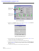
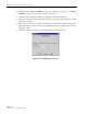


Table Of Contents

ADCP-75-126 • Issue B • April 2002 • Section 5: Maintenance
Page 5-2
©
2002,
ADC
Telecommunications,
Inc.
•Battery
maintenance
tools
(see
PRC-SERIES
OPERATING
AND
FIELD
SERVICE
MANUAL
for
tool
recommendations)
2 FAULT DETECTION AND ALARM REPORTING
The
Digivance
LRCS
on-board
embedded
software
detects
various
unit
and
system
faults
and
reports
them
as
either
Major
or
Minor
alarms.
A
Major
alarm
indicates
that
the
system
has
failed
in
a
way
that
directly
affects
RF
transport
performance.
This
usually
means
that
some
calls
or
perhaps
all
calls
cannot
be
made
over
the
system.
A
Minor
alarm
means
that
system
performance
is
not
affected
or
in
some
cases,
that
the
performance
may
no
longer
be
optimal.
Four
types
of
faults
cause
a
minor
alarm
to
be
reported:
overtemperature,
fan
failure,
diversity
path
failure,
and
an
external
minor
fault
(user
defined
fault).
All
other
faults
are
reported
as
a
Major
alarm.
Reporting
of
Major
and
Minor
alarms
is
accomplished
through
the
HU
alarm
contacts,
the
unit
front
panel
LED’s,
the
EMS
software
Graphical
User
Interface
(GUI),
and
the
Network
Operations
Center
-
Network
Element
Manager
(NOC/NEM)
interface.
The
HU
is
equipped
with
a
set
of
both
normally
open
(NO)
and
normally
closed
(NC)
alarm
contacts
which
are
used
to
report
both
Major
and
Minor
alarms
to
an
external
alarm
system.
The
alarm
contacts
summarize
the
inputs
so
that
any
Major
or
Minor
alarm
will
trigger
an
alarm
report
to
the
external
alarm
system.
The
HU,
STM,
and
LPA
front
panel
LED
indicators
are
used
to
report
specific
alarms
which
are
reflected
in
the
LED
colors:
Green,
Red,
Yellow,
and
Off.
In
addition
to
LED
indicators,
the
LPA
is
also
equipped
with
a
Digital
Display
that
provides
status
messages.
A
description
of
the
Host
Unit,
Spectrum
Transport
Module,
and
Linear
Power
Amplifier
LED
indicators
is
provided
respectively
in
Table 5-1,
Table 5-2,
and
Table 5-3.
The
EMS
software
GUI
provides
both
a
summary
and
a
more
detailed
list
of
alarm
information
that
includes
unit
and
module
level
faults,
circuit
faults,
and
measured
value
faults
such
as
voltages,
RF
power,
and
temperature.
A
summary
showing
a
list
of
all
systems
and
their
current
alarm
status
is
presented
through
the
Alarm
OverView
display.
A
detailed
list
of
alarm
information
is
presented
through
the
HOST
alarm
display
and
the
REMOTE
alarm
display.
All
the
inputs
that
the
system
reports
as
alarms
are
shown
in
the
HOST
and
REMOTE
alarm
displays.
The
NOC/NEM
interface
provides
the
same
summary
and
detailed
list
of
alarm
information
as
the
EMS
software
GUI
but
in
an
ASCII
text
string
format.
Sending
the
command
GET
ALARMSUMMARY
produces
a
list
of
all
systems
and
their
current
alarm
status.
Sending
the
command
GET
ALARM
ALL
for
a
specific
system
will
produce
a
detailed
list
of
alarm
information
for
the
specified
system.