
User Manual
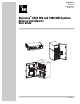
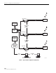
Table Of Contents
- ABOUT THIS MANUAL
- RELATED PUBLICATIONS
- ADMONISHMENTS
- GENERAL SAFETY PRECAUTIONS
- STANDARDS CERTIFICATION
- LIST OF ACRONYMS AND ABBREVIATIONS
- 1 DESCRIPTION
- 2 HARDWARE AND SOFTWARE REQUIREMENTS
- 3 APPLICATION
- 4 EMS SOFTWARE GRAPHICAL USER INTERFACE
- 5 TROUBLESHOOTING AN RLM ALARM
- 6 CUSTOMER INFORMATION AND ASSISTANCE

ADCP-75-191 • Preliminary Issue B • November 2005
Page 4
© 2005, ADC Telecommunications, Inc.
5 TROUBLESHOOTING AN RLM ALARM
An RLM alarm indicates that the level of the reverse path RF signal has dropped by 10 dBm as
referenced against a pilot tone injected at the STM and measured at the Host Unit. The reverse
path gain is provided on a system level by both the Host Unit and the Remote Unit (STM).
Together, the Host Unit and Remote Unit (STM) provide 30 dBm of gain in the reverse path.
When an RLM alarm occurs, the problem could be within either the STM or the Host Unit. If
replacing one unit does not clear the alarm, the fault is within other unit.