
User Manual
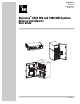

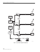
Table Of Contents
- ABOUT THIS MANUAL
- RELATED PUBLICATIONS
- ADMONISHMENTS
- GENERAL SAFETY PRECAUTIONS
- STANDARDS CERTIFICATION
- LIST OF ACRONYMS AND ABBREVIATIONS
- 1 DESCRIPTION
- 2 HARDWARE AND SOFTWARE REQUIREMENTS
- 3 APPLICATION
- 4 EMS SOFTWARE GRAPHICAL USER INTERFACE
- 5 TROUBLESHOOTING AN RLM ALARM
- 6 CUSTOMER INFORMATION AND ASSISTANCE

ADCP-75-191 • Preliminary Issue B • November 2005
Page 1
© 2005, ADC Telecommunications, Inc.
1 DESCRIPTION
The Reverse Link Monitor (RLM) is an optional add-on feature that is available for the
Digivance 800 and 1900 MHz LRCS product line. The RLM feature provides an alarm indication
if there is a loss of gain in the reverse path RF signal. The standard Digivance product provides
an alarm indication if there is an internal component failure or an optical failure but does not
provide an alarm if a loss of gain occurs in the reverse path RF signal.
The RLM feature works by injecting a pilot tone at the STM and then measuring the level of the
tone at the Host Unit. An RLM fault is reported if the reverse path signal level at the Host Unit
RF output drops more than 10 dBm. This generates a major alarm which triggers the operation of
the normally open and normally closed alarm contacts provided by the Host Unit. The RLM
feature is available on both non-diversity and diverstiy systems. On diversity systems, an RLM
fault in either the primary or diversity return path will trigger an RLM alarm.
The RLM alarm generates an alarm message which may be accessed through the Element
Management System (EMS) software, the Network Operations Center-Network Element
Manager (NOC-NEM) interface, or the Simple Network Management Protocol (SNMP)
manager. The Host Unit (LED) indicators on both the Host Unit and the Remote unit (STM)
turn red when an RLM alarm is reported. The RF output of the Remote Unit is not muted for an
RLM alarm.
2 HARDWARE AND SOFTWARE REQUIREMENTS
The RLM feature requires that both the Host Unit and the Remote Unit Spectrum Transport
Unit (STM) be equipped with the internal components that support RLM. This is an option that
must be specified when either unit is ordered. There are no external markings that indicate if the
Host Unit or STM supports RLM. Host Units and STM’s equipped with the RLM feature are
compatible with hardware that does not support the RLM feature. However, the RLM feature
will not function unless both units are equipped to support the RLM feature.
The EMS and SNMP agent software has been upgraded to support the RLM feature. Only EMS
software Version 7.0 and SNMP Agent software Version 7.1 can report when an RLM alarm has
been generated. The upgraded versions of the EMS and SNMP agent software are compatible
with any earlier versions of the Host Unit and STM that are not equipped with the RLM feature.
Earlier versions of the EMS and SNMP agent software (Version 3.01 and Version 5.0) do not
support RLM alarm reporting but are otherwise compatible with RLM equipped hardware.
3 APPLICATION
The RLM feature is primarily designed for simulcast applications where a single Base
Transceiver Station (BTS) is configured to serve multiple Host Units as shown in Figure 1. The
BTS monitors the level of the reverse path RF signal and generates an alarm if the level drops
below a specified threshold. When a single Host Unit is connected to the BTS, a drop in the
reverse path signal level will generate an alarm by the BTS. When several Host Units are linked
to the same BTS, a drop in the reverse path signal level from one of the Host Units will not
generate an alarm if the reverse path RF signal levels from the remaining units are within
specifications. The RLM feature provides selective alarming that cannot be provided by the
BTS in a simulcast application.