
User Manual
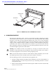


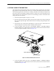
Table Of Contents

ADCP-75-126 • Issue B • April 2002 • Section 3: Host Unit Installation
Page 3-9
©
2002,
ADC
Telecommunications,
Inc.
In
many
installations,
it
is
usually
necessary
to
install
an
external
attenuator
in
the
forward
path
link
between
the
HU
and
the
BTS.
The
procedure
for
determining
the
value
of
the
external
attenuator
is
provided
in
SECTION
4:
OPERATION.
The
HU
should
be
mounted
as
close
as
possible
to
the
BTS
to
minimize
cable
losses.
Use
the
following
procedure
to
route
the
forward
and
reverse
path
coaxial
cables
and
connect
them
to
the
HU:
1. Obtain
the
required
lengths
of
high
performance,
flexible,
low
loss
50-ohm
coaxial
communications
cable
(RG-400
or
equivalent)
for
all
coaxial
connections.
2. Route
the
forward
and
reverse
path
coaxial
cables
and
the
diversity
reverse
path
cable
(if
the
HU
supports
diversity)
between
the
HU
and
the
BTS
interface
(per
system
design
plan)
and
cut
to
the
required
length.
Allow
sufficient
slack
for
dressing
and
organizing
cables
at
the
HU
and
for
installing
an
external
attenuator
in
the
forward
path
link.
3. Terminate
each
cable
with
a
type
N
male
connector
following
the
connector
supplier’s
recommendations.
4. Connect
the
forward
path
cable
to
the
FORWARD
RF
IN
connector
on
the
HU
front
panel
as
shown
in
Figure 3-8.
Figure 3-8. Forward and Reverse Path Coaxial Cable Connections
5. Connect
the
reverse
path
cable
to
the
REVERSE
RF
OUT
connector
on
the
HU
front
panel
(see
Figure 3-8).
6. If
the
HU
supports
diversity,
connect
the
diversity
reverse
path
cable
to
the
REVERSE
2
RF
OUT
connector
on
the
HU
front
panel
(see
Figure 3-8).
7. Dress
and
secure
cables
at
the
HU.
8. Complete
all
remaining
coaxial
connections
at
the
BTS
interface
as
specified
in
the
system
design
plan.
16887-A
TYPE-N MALE
CONNECTOR
FORWARD RF IN
CONNECTOR
(FORWARD PATH)
REVERSE
RF OUT CONNECTOR
(REVERSE PATH)
REVERSE 2
RF OUT CONNECTOR
(DIVERSITY REVERSE PATH)