
User Manual
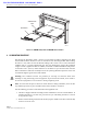

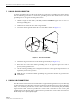

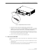


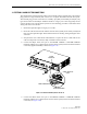
Table Of Contents

ADCP-75-126 • Issue B • April 2002 • Section 3: Host Unit Installation
Page 3-10
©
2002,
ADC
Telecommunications,
Inc.
7 OPTICAL CONNECTIONS
The
optical
interface
between
the
HU
and
the
RU
is
supported
by
either
two
(non-diversity)
or
three
(diversity)
optical
ports.
Each
optical
port
consists
of
an
SC
optical
adapter
which
is
mounted
on
the
HU
front
panel.
Port
1
provides
the
optical
fiber
connection
for
the
forward
path
(downlink)
signal.
Port
2
provides
the
optical
fiber
connection
for
the
reverse
path
(uplink)
signal.
Port
3
provides
the
optical
fiber
connection
for
the
diversity
reverse
path
(uplink)
signal.
The
optical
connections
are
dependent
on
whether
or
not
a
WDM
(optional
accessory)
is
installed.
If
the
installation
does
not
include
a
WDM,
proceed
to
Section
7.1
for
the
optical
connections
procedure.
If
the
installation
does
include
a
WDM,
proceed
to
Section
7.2
for
the
optical
connections
procedure.
7.1 Optical Connections Without WDM
Use
the
following
procedure
to
connect
the
optical
fibers
when
a
WDM
is
not
installed
with
the
HU:
1. Obtain
two
(non-diversity)
or
three
(diversity)
patch
cords
that
are
of
sufficient
length
to
reach
from
the
HU
to
the
fiber
distribution
panel.
2. Designate
one
of
the
patch
cords
as
the
forward
path
link
and
the
other
as
the
reverse
path
link
and
attach
an
identification
label
or
tag
next
to
the
connector.
For
diversity
systems,
designate
and
label
or
tag
a
third
patch
cord
as
the
diversity
reverse
path
link.
3. Remove
the
dust
caps
from
the
HU
optical
ports
and
from
the
patch
cord
connectors
that
will
be
connected
to
the
HU.
4. Clean
each
patch
cord
connector
(follow
connector
supplier’s
recommendations)
and
then
insert
the
connector
into
the
appropriate
optical
port
as
shown
in
Figure 3-9
and
as
specified
by
the
following:
Port
1
-
Forward
path
patch
cord
Port
2
-
Reverse
path
patch
cord
Port
3
-
Diversity
reverse
path
patch
cord
5. Route
the
patch
cords
from
the
HU
to
the
fiber
distribution
panel.
Danger:
This
equipment
uses
a
Class
1
Laser
according
to
FDA/CDRH
rules.
Laser
radiation
can
seriously
damage
the
retina
of
the
eye.
Do
not
look
into
the
ends
of
any
optical
fiber.
Do
not
look
directly
into
the
optical
transmitter
of
any
unit
or
exposure
to
laser
radiation
may
result.
An
optical
power
meter
should
be
used
to
verify
active
fibers.
A
protective
cap
or
hood
MUST
be
immediately
placed
over
any
radiating
transmitter
or
optical
fiber
connector
to
avoid
the
potential
of
dangerous
amounts
of
radiation
exposure.
This
practice
also
prevents
dirt
particles
from
entering
the
connector.
Note:
The
HU
optical
adapters
are
angled
to
the
left.
Therefore,
patch
cords
should
always
be
routed
to
the
HU
from
the
left
side
of
the
rack.
Routing
patch
cords
to
the
HU
from
the
right
side
of
the
rack
may
exceed
the
bend
radius
limitations
for
the
optical
fiber.