
User Manual
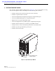


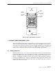


Table Of Contents

ADCP-75-126 • Issue B • April 2002 • Section 2: Description
Page 2-13
©
2002,
ADC
Telecommunications,
Inc.
4.1 Primary Components
The
STM
consists
of
an
electronic
circuit
board
assembly,
power
supply,
duplexer,
and
fan
assembly
that
are
mounted
within
a
powder-coated
sheet
metal
enclosure.
The
metal
enclosure
provides
a
mounting
point
for
the
electronic
components
and
controls
RF
emissions.
Except
for
the
fan
unit,
the
electronic
components
are
not
user
replaceable.
The
STM
is
designed
for
use
within
the
RU
cabinet.
Except
for
the
LPA
interface
connector,
all
controls,
connectors,
indicators,
and
switches
are
mounted
on
the
STM
front
panel
for
easy
access.
A
carrying
handle
is
provided
on
the
front
of
the
STM
to
facilitate
installation
and
transport.
4.2 Mounting
The
STM
mounts
on
a
shelf
within
the
RU
cabinet.
A
runner
on
the
bottom
of
the
STM
meshes
with
a
track
on
the
mounting
shelf.
The
runner
and
track
guide
the
STM
into
the
installed
position.
The
electrical
interface
between
the
STM
and
LPA
is
supported
by
a
D-sub
female
connector
located
on
the
rear
side
of
the
STM.
A
corresponding
D-sub
male
connector
mounted
at
the
rear
of
the
RU
cabinet
mounting
shelf
mates
with
the
STM
connector.
Captive
screws
are
provided
for
securing
the
STM
to
the
mounting
shelf.
4.3 Fault Detection and Alarm Reporting
The
STM
detects
and
reports
various
faults
including
remote
unit
fault,
optical
fault,
power
fault,
temperature
fault,
power
amplifier
fault,
and
external
(door
open)
fault.
Various
front
panel
Light
Emitting
Diode
(LED)
indicators
turn
from
green
to
red
or
yellow
if
a
fault
is
detected.
The
status
of
the
STM,
the
alarm
state
(major
or
minor),
and
other
alarm
information
is
summarized
and
reported
over
the
optical
fiber
to
the
HU
and
also
over
the
service
interface.
In
addition,
the
alarm
state
of
the
HU
is
received
over
the
optical
fiber
and
reported
to
the
service
interface.
This
information
may
be
accessed
remotely
through
the
NOC/NEM
interface
or
locally
through
the
EMS
software
GUI.
4.4 Antenna Cable Connection
The
antenna
cable
connections
between
the
STM
and
the
antenna
are
supported
through
either
one
(non-diversity
unit)
or
two
(diversity
unit)
N-type
female
connectors.
On
non-diversity
units,
a
single
connector
is
used
for
the
antenna
cable
which
carries
both
the
forward
and
primary
reverse
path
RF
signals.
On
diversity
units,
a
second
connector
is
used
for
the
diversity
antenna
cable
which
carries
only
the
diversity
reverse
path
RF
signals.
The
STM
does
not
connect
directly
to
the
antenna
but
instead
connects
to
a
lightning
protector
that
is
mounted
on
the
bottom
of
the
RU
cabinet
(see
Section
3.5).
A
coaxial
jumper
cable
is
provided
(included
with
the
enclosure)
for
connecting
the
STM
connector
to
the
lightning
protector.
4.5 RF Signal Level Adjustment
The
STM
is
equipped
with
a
digital
attenuator
for
adjusting
the
signal
level
of
the
forward
path
RF
output
signal.
The
remote
forward
path
attenuator
adjusts
the
level
of
the
output
RF
signal
at
the
RU
antenna
port
and
will
add
from
0
to
30
dB
of
attenuation
to
the
output
signal
level.