
User Manual
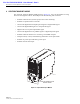


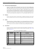
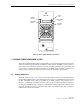


Table Of Contents

ADCP-75-126 • Issue B • April 2002 • Section 2: Description
Page 2-15
©
2002,
ADC
Telecommunications,
Inc.
Figure 2-6. Spectrum Transport Module User Interface
Table 2-3. Spectrum Transport Module User Interface
REF
NO
USER INTERFACE
DESIGNATION
DEVICE
FUNCTIONAL
DESCRIPTION
1PORT
1SC
connector
(single-mode)
Connection
point
for
the
forward
path
optical
fiber.
2PORT
2SC
connector
(single-mode)
Connection
point
for
the
reverse
path
primary
optical
fiber.
3PORT
3
(diversity
unit
only)
SC
connector
(single-mode)
Connection
point
for
the
reverse
path
diversity
optical
fiber.
41/0 On/Off
rocker
switch
Provides
AC
power
on/off
control.
5No
designation 3-wire
AC
power
cord
connector
Connection
point
for
the
AC
power
cord.
6No
designation 2-
wire
DC
power
cord
connector
Connection
point
for
the
back-up
battery
power
cord.
7 SERVICE DB-9
connector
(female)
Connection
point
for
the
RS-232
service
inter-
face
cable.
17527-A
(4) ON/OFF
SWITCH
(5) AC POWER
CONNECTOR
(6) DC POWER
CONNECTOR
(1) PORT 1
CONNECTOR
(2) PORT 2
CONNECTOR
(3) PORT 3
CONNECTOR
NOTE: UNIT SHOWN INCLUDES
DIVERSITY OPTION
(7) SERVICE
CONNECTOR
(8-15) LED
INDICATORS
(16) ALARM
CONNECTOR
(17) DIVERSITY
ANTENNA
CONNECTOR
(18) ANTENNA
CONNECTOR