
User Manual
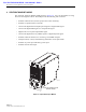


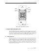


Table Of Contents

ADCP-75-126 • Issue B • April 2002 • Section 2: Description
Page 2-16
©
2002,
ADC
Telecommunications,
Inc.
5 LINEAR POWER AMPLIFIER
The
Linear
Power
Amplifier
(LPA),
shown
in
Figure 2-7,
works
is
conjunction
with
the
STM
to
amplify
the
forward
path
RF
output
signal.
The
STM
is
interfaced
with
the
LPA
through
the
D-
sub
connectors
and
wiring
harness
located
at
the
rear
of
the
RU
cabinet.
The
RF
signal
is
passed
to
the
LPA
for
amplification
and
then
passed
back
to
the
STM
for
output
via
the
STM’s
ANTENNA
port.
The
STM
also
supplies
DC
power
to
the
LPA
through
the
same
interface.
8AC
POWER Multi-colored
LED
(green/red)
Indicates
if
the
STM
is
powered
by
the
AC
power
source
(green)
or
the
back-up
battery
system
(red).
See
Note.
9 STANDBY Multi-colored
LED
(green/yellow/red)
Indicates
if
the
system
is
in
the
Normal
state
(off)
Standby
state
(blinking
green),
Test
state
(blink-
ing
red),
or
Program
Load
state
(blinking
yel-
low).
See
Note.
10 HOST
UNIT Multi-colored
LED
(green/yellow/red)
Indicates
if
no
alarms
(green),
a
minor
alarm
(yellow),
or
a
major
alarm
(red)
is
detected
at
the
HU.
See
Note.
11 STM Multi-colored
LED
(green/yellow/red)
Indicates
if
the
STM
is
normal
(green)
or
faulty
(red).
See
Note.
12 PA Multi-colored
LED
(green/yellow/red)
Indicates
if
the
power
amplifier
is
normal
(green),
over
temperature
(yellow),
has
a
fan
fail-
ure
(yellow),
or
is
faulty
(red).
See
Note.
13 VSWR Multi-colored
LED
(green/yellow/red)
Indicates
if
the
forward
path
VSWR
is
above
(red)
or
below
(green)
the
fault
threshold.
14 PORT
1/PORT
2 Multi-colored
LED
(green/yellow/red)
Indicates
if
the
forward
path
optical
signal
received
from
the
HU
is
normal
(green),
if
no
sig-
nal
is
detected
(red),
or
if
errors
are
detected
(red).
See
Note.
15 PORT
3
(diversity
unit
only)
Multi-colored
LED
(green/yellow)
Indicates
if
the
diversity
reverse
path
optical
sig-
nal
received
by
the
HU
is
normal
(green),
if
no
signal
is
detected
(yellow),
or
if
errors
are
detected
(yellow).
See
Note.
16 ALARM
IN
MINOR
ALARM
IN
MAJOR
Screw-type
terminal
connector
(14–26
AWG)
Connection
point
for
two
external
alarm
inputs.
The
door-open
switch
lead
wires
are
typically
connected
to
the
major
alarm
terminals.
17 DIVERSITY
(diversity
unit
only)
N-type
female
RF
coaxial
connector
Connection
point
for
the
diversity
antenna.
18 ANTENNA N-type
female
RF
coaxial
connector
Connection
point
for
the
primary
antenna.
Note:
A
more
detailed
description
of
LED
operation
is
provided
in
Section
5.
Table 2-3. Spectrum Transport Module User Interface, continued
REF
NO
USER INTERFACE
DESIGNATION
DEVICE
FUNCTIONAL
DESCRIPTION