
User Manual
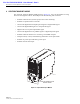


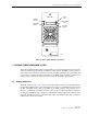


Table Of Contents

ADCP-75-126 • Issue B • April 2002 • Section 2: Description
Page 2-18
©
2002,
ADC
Telecommunications,
Inc.
5.3 Fault Detection and Alarm Reporting
The
LPA
in
conjunction
with
the
STM
detects
and
reports
various
faults
including
power
amplifier
fault,
output
power
fault,
temperature
fault,
and
fan
fault.
Various
Light
Emitting
Diode
(LED)
indicators,
located
on
the
front
panels
of
both
the
STM
and
LPA,
turn
from
green
to
red
or
yellow
if
an
LPA
fault
is
detected.
In
addition,
a
digital
display
located
on
the
LPA
front
panel
provides
various
fault
messages.
The
status
of
the
LPA,
the
alarm
state
(major
or
minor),
and
other
more
detailed
information
is
summarized
and
reported
(by
the
STM)
over
the
optical
fiber
to
the
HU
and
also
to
the
service
interface.
This
detailed
information
may
be
accessed
remotely
through
the
NOC/NEM
interface
or
locally
through
the
EMU
software
GUI.
5.4 Powering
The
LPA
is
powered
by
various
DC
voltages
which
are
supplied
by
the
STM
over
the
electrical
interface
provided
by
the
D-sub
connectors
and
wiring
harness
mounted
within
the
RU
cabinet.
5.5 Cooling
Continuous
air-flow
for
cooling
is
provided
by
a
pair
of
fans
mounted
at
the
front
and
the
rear
side
of
the
LPA
housing.
The
front
fan
pulls
cool
air
into
the
module
and
the
rear
fan
exhausts
heated
air
out
of
the
module.
An
alarm
is
provided
that
indicates
if
a
high
temperature
condition
(>50º
C/122º
F)
occurs
or
if
a
fan
failure
occurs.
Either
fan
may
be
field
replaced
if
it
fails.
5.6 User Interface
The
LPA
user
interface
consists
of
the
various
LEDs,
message
displays,
and
switches
that
are
provided
on
the
LPA
front
panel.
The
LPA
user
interface
points
are
described
in
Table 2-4
and
indicated
in
Figure 2-8.
Table 2-4. Linear Power Amplifier User Interface
REF
NO
USER INTERFACE
DESIGNATION
DEVICE
FUNCTIONAL
DESCRIPTION
1 RESET Momentary
contact
push
button
switch
Momentarily
pressing
the
switch
push
button
clears
all
alarms
and
restarts
the
amplifier
2RF
ON
OFF 2-position
switch Placing
the
switch
in
the
OFF
position
puts
the
LPA
in
a
standby
state
with
RF
output
disabled.
Placing
the
switch
in
the
ON
position
puts
the
LPA
in
the
normal
state
with
RF
output
enabled.
3FAIL LED
indicator
(yellow)
Indicates
the
LPA
is
normal
(off)
or
faulty
(yellow).
4 SHUTDOWN LED
indicator
(red) Indicates
the
LPA
is
in
service
(off)
or
shutdown
(red).
5No
designation Digital
display Provides
status
and
alarm
messages.
See
Note.
Note:
A
more
detailed
description
of
the
digital
display
messages
is
provided
in
Section
5.