ADC-100 PC Oscilloscope User's Guide adc100.en-2 © Copyright 2004-2007 Pico Technology Limited. All rights reserved.
I ADC-100 User's Guide Contents 1 Introduction .....................................................................................................................................1 ...........................................................................................................................................1 1 Overview ...........................................................................................................................................1 2 Installing the driver ...........
Introduction 1 Introduction 1.1 Overview 1 The Pico ADC-100 and ADC-101 are medium-speed analog-to-digital converters with two analog input channels and programmable input voltage ranges. They can be used as a virtual instrument (oscilloscope, spectrum analyser and meter) with the PicoScope program, or as a data logger using PicoLog. Alternatively, you can use the ADC-100 driver software to develop your own programs to collect and analyse data from the unit.
2 1.4 ADC-100 User's Guide Software configuration Checking the installation To check that the unit is working, start up the PicoScope program and then connect a voltage source to the BNC connector. The ADC has the same connectors as an oscilloscope, so you can use standard oscilloscope probes. PicoScope should now display the voltage that you have connected. If you are using scope probes, when you touch the scope probe tip with your finger, you should see a small 50 Hz or 60 Hz signal on the screen.
Introduction 3 Repairs The unit contains no user-serviceable parts: repair or calibration of the unit requires specialised test equipment and must be performed by Pico Technology Limited or their authorised distributors. 1.6 Legal information The material contained in this release is licensed, not sold. Pico Technology Limited grants a license to the person who installs this software, subject to the conditions listed below.
4 ADC-100 User's Guide Trademarks Pico Technology Limited, PicoScope, PicoLog, DrDAQ and EnviroMon are trademarks of Pico Technology Limited, registered in the United Kingdom and other countries. Pico Technology acknowledges the following product names as trademarks of their respective owners: Windows, Excel, Visual Basic, LabVIEW, Agilent VEE, HP VEE, Delphi. 1.
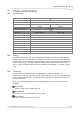
Product information 2 Product information 2.1 Specifications ADC-100 Resolution Channels Voltage ranges Overload protection Input impedance ADC-101 12 bits 2 x BNC ±50 mV to ±20 V in 9 ±100 mV to ±100 V in 9 ranges ranges ±100 V 1 MW Input type Maximum sampling rate Linearity Accuracy Scope timebases Spectrum ranges Analog bandwidth Buffer size Power supply Dimensions Output connector 2.
6 ADC-100 User's Guide BM_SINGLE is useful when you wish to collect data at high speed for a relatively short period. For example, to collect 1000 readings in 50 ms. BM_WINDOW is useful when collecting several blocks of data at relatively low speeds- for example when collecting 10000 samples over 10 seconds. Collecting a sequence of SINGLE blocks like this would take 10 seconds for each block, so displayed data would not be updated frequently.
Technical reference 3 Technical reference 3.1 Introduction 7 The ADC-100 and ADC-101 are supplied with driver routines that you can build into your own programs. Once you have installed the software, the DRIVERS sub-directory contains the drivers and a selection of examples of how to use the drivers. It also contains a copy of this help file in text format. The driver routines are supplied as Dynamic Link Libraries for Windows 95/98/ME and NT/200/XP.
8 ADC-100 User's Guide Under Windows, if you connect the product to the computer via a Pico USB parallel port, timing is completely reliable. However, if you connect the product to the computer via the printer port, the sampling may be affected by Windows activities. At the least, there will be gaps in the data every 55 milliseconds due to the Windows timer function. There will be additional gaps if you move the mouse, or have other programs running.
Technical reference 3.3 Driver routines 3.3.1 adc100_get_driver_version 9 PREF1 short PREF2 adc100_get_driver_version (void); This routine returns the version number of the ADC100/101 driver. You can use it to check that your application is used only with the driver version that it was designed for use with.
10 3.3.4 ADC-100 User's Guide adc100_set_unit PREF1 short PREF2 adc100_set_unit ( short port); This routine is used to select the unit to use for subsequent operations. It is only necessary to use this function if you wish to have more than one unit open at the same time. Arguments: Returns: 3.3.5 adc100_set_range PREF 1 void PREF2 adc100_set_range ( short mv_a, short mv_b); This routine sets the range for both channels.
Technical reference 3.3.6 11 adc100_get_value PREF 1 short PREF2 adc100_get_value ( short channel); This routine reads the current value of one channel. Depending on your computer, it will take approx 20µs to take one reading. Arguments: channel 0 - channel A 1 - channel B Returns: 3.3.7 adc100_is_streaming short adc100_is_streaming (void) This routine can be used to determine whether the device is capable of supporting streaming. If so, it will return TRUE (1).
12 3.3.9 ADC-100 User's Guide adc100_ready short adc100_ready (void) This routine indicates whether a streaming device has completed its data collection. Arguments: none Returns: - TRUE if the device is ready to transfer data. For non-streaming devices, it always return TRUE 3.3.10 adc100_stop void adc100_stop (void) This function cancels any pending request for data from a streaming device. It has no effect for non-streaming devices. Arguments: none Returns: adc100.
Technical reference 13 3.3.11 adc100_set_trigger PREF1 void unsigned unsigned unsigned unsigned unsigned unsigned unsigned PREF2 short short short short short short short adc100_set_trigger ( enabled, auto_trigger, auto_ms, channel, dir, threshold, delay); This routine defines a trigger event for the next block operation, and specifies the delay between the trigger event and the start of collecting the data block. Note that the delay can be negative for pre-trigger.
14 ADC-100 User's Guide 3.3.12 adc100_set_interval PREF1 unsigned long PREF2 adc100_set_interval ( unsigned long us_for_block, unsigned long ideal_no_of_samples, short mode); This routine specifies the time interval per sample and the channels to be used for calls to adc100_get_values or adc100_get_times_and_values. An example of a call to this routine using both channels A and B is: adc100_set_interval (10000, 100, 2); The routine returns the actual time to collect this number of samples.
Technical reference 15 3.3.13 adc100_get_values PREF 1 unsigned long PREF2 adc100_get_values ( unsigned short HUGE * buffer_a, unsigned short HUGE * buffer_b, unsigned long no_of_values); This routine reads in a block of values. It collects readings at intervals and from channels specified in the most recent adc100_set_interval call. If a key is pressed while collecting, the routine will return immediately.
16 ADC-100 User's Guide 3.3.14 adc100_get_times_and_values PREF1 unsigned long PREF2 adc100_get_times_and_values ( long HUGE * times, unsigned short HUGE * buffer_a, unsigned short HUGE * buffer_b, unsigned long no_of_values); This routine reads a block of values from the unit in the most recent adc100_open_unit or adc100_set_unit call. It takes readings at nominal intervals specified in the most recent adc100_set_interval call, and returns the actual times for each reading.
Technical reference 17 3.3.16 adc100_get_combined_values PREF1 unsigned long PREF2 adc100_get_combined_values ( UNS16 channel, COMBINATION_METHOD mode, /* Combination modes (CM_XXX) */ UNS16 no_of_readings ) This routine takes a set of readings from the specified channel, at full speed, and returns either the minimum, maximum, average or sum of the set of readings.
18 ADC-100 User's Guide 3.4 Programming 3.4.1 C / C++ C There are two C example programs: one is a very simple GUI application, and the other is a more comprehensive console mode program that demonstrates all of the facilities of the driver. The GUI example program is a generic windows application- ie it does not use Borland AppExpert or Microsoft AppWizard. To compile the program, create a new project for a Windows Application containing the following files: a100test.c a100test.rc either adc10032.
Technical reference 3.4.3 19 Excel The easiest way to transfer data into Excel is to use PicoLog. However, you can also write an Excel macro which calls adc100xx.dll to read in a set of data values. The Excel Macro language is similar to Visual Basic. The example ADC100xx.XLS reads in 20 values from channels 1 and 2, one per second, and assigns them to cells A1..B20. Note that it is usually necessary to copy the .DLL file to your directory. 3.4.
20 adc100.en ADC-100 User's Guide © Copyright 2004-2007 Pico Technology Limited. All rights reserved.
Index Index 21 Specification 5 Streaming 5 V A Visual Basic adc100_close_unit 9 adc100_get_combined_values 17 adc100_get_times_and_values 16 adc100_get_unit_info 16 adc100_get_value 11 adc100_get_values 15 adc100_is_streaming 11 adc100_open_unit 9 adc100_ready 12 adc100_run 11 adc100_set_interval 14 adc100_set_trigger 13 adc100_set_unit 10 adc100_stop 12 19 W Windows NT 8 C C 18 C++ 18 Contact details 4 D Delphi 18 Drivers 7 E Excel 19 H HP-Vee 19 I Installation 1 Introduction 1 L Labview
22 adc100.en ADC-100 User's Guide © Copyright 2004-2007 Pico Technology Limited. All rights reserved.
Pico Technology Ltd The Mill House Cambridge Street St Neots PE19 1QB United Kingdom Tel: +44 (0) 1480 396 395 Fax: +44 (0) 1480 396 296 Web: www.picotech.com adc100.en 1.10.07 © Copyright 2004-2007 Pico Technology Limited. All rights reserved.