
Specifications


GND
V
A
100 k:
GND
V
A
100 k:
GND
V
A
50 k:
GND
V
A
GND
V
A
ADC12D1000RF, ADC12D1600RF
SNAS519G –JULY 2011–REVISED APRIL 2013
www.ti.com
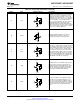
Table 2-2. Control and Status Balls (continued)
Ball No. Name Equivalent Circuit Description
Full-Scale input Range select. In Non-ECM, when
this input is set to logic-low or logic-high, the full-
scale differential input range for both I- and Q-
channel inputs is set to the lower or higher FSR
value, respectively. In the ECM, this input is
Y3 FSR
ignored and the full-scale range of the I- and Q-
channel inputs is independently determined by the
setting of Addr: 3h and Addr: Bh, respectively.
Note that the high (lower) FSR value in Non-ECM
corresponds to the mid (min) available selection in
ECM; the FSR range in ECM is greater.
DDR Phase select. This input, when logic-low,
selects the 0° Data-to-DCLK phase relationship.
When logic-high, it selects the 90° Data-to-DCLK
phase relationship, i.e. the DCLK transition
indicates the middle of the valid data outputs. This
W4 DDRPh pin only has an effect when the chip is in 1:2
Demuxed Mode, i.e. the NDM pin is set to logic-
low. In ECM, this input is ignored and the DDR
phase is selected through the Control Register by
the DPS Bit (Addr: 0h, Bit 14); the default is 0°
Mode.
Extended Control Enable bar. Extended feature
control through the SPI interface is enabled when
this signal is asserted (logic-low). In this case,
most of the direct control pins have no effect.
B3 ECE
When this signal is de-asserted (logic-high), the
SPI interface is disabled, all SPI registers are
reset to their default values, and all available
settings are controlled via the control pins.
Serial Chip Select bar. In ECM, when this signal is
asserted (logic-low), SCLK is used to clock in
serial data which is present on SDI and to source
C4 SCS
serial data on SDO. When this signal is de-
asserted (logic-high), SDI is ignored and SDO is in
tri-stated.
Serial Clock. In ECM, serial data is shifted into
and out of the device synchronously to this clock
C5 SCLK signal. This clock may be disabled and held logic-
low, as long as timing specifications are not
violated when the clock is enabled or disabled.
10 Device Information Copyright © 2011–2013, Texas Instruments Incorporated
Submit Documentation Feedback
Product Folder Links: ADC12D1000RF ADC12D1600RF