
Specifications

ADC12D1000RF, ADC12D1600RF
www.ti.com
SNAS519G –JULY 2011–REVISED APRIL 2013
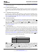
Table 6-1. Non-ECM Pin Summary
Pin Name Logic-Low Logic-High Floating
Dedicated Control Pins
DES
DES Non-DES Mode Not valid
Mode
Demux
NDM Non-Demux Mode Not valid
Mode
DDRPh 0° Mode / Falling Mode 90° Mode / Rising Mode Not valid
CAL See Calibration Pin (CAL) Not valid
CalDly Shorter delay Longer delay Not valid
Power Down Power Down
PDI I-channel active
I-channel I-channel
Power Down Power Down
PDQ Q-channel active
Q-channel Q-channel
TPM Non-Test Pattern Mode Test Pattern Mode Not valid
FSR Lower FS input Range Higher FS input Range Not valid
Dual-purpose Control Pins
V
CMO
AC-coupled operation Not allowed DC-coupled operation
Higher LVDS common-mode Lower LVDS common-mode
V
BG
Not allowed
voltage voltage
6.2.1.1 Dual Edge Sampling Pin (DES)
The Dual Edge Sampling (DES) Pin selects whether the ADC12D1600/1000RF is in DES Mode (logic-
high) or Non-DES Mode (logic-low). DES Mode means that a single analog input is sampled by both I-
and Q-channels in a time-interleaved manner. One of the ADCs samples the input signal on the rising
sampling clock edge (duty cycle corrected); the other ADC samples the input signal on the falling sampling
clock edge (duty cycle corrected). In Non-ECM, only the I-input may be used for DES Mode, a.k.a. DESI
Mode. In ECM, the Q-input may be selected via the DEQ Bit (Addr: 0h, Bit: 6), a.k.a. DESQ Mode. In
ECM, both the I- and Q-inputs may be selected, a.k.a. DESIQ or DESCLKIQ Mode.
To use this feature in ECM, use the DES bit in the Configuration Register (Addr: 0h; Bit: 7). See
DES/Non-DES Mode for more information.
6.2.1.2 Non-Demultiplexed Mode Pin (NDM)
The Non-Demultiplexed Mode (NDM) Pin selects whether the ADC12D1600/1000RF is in Demux Mode
(logic-low) or Non-Demux Mode (logic-high). In Non-Demux Mode, the data from the input is produced at
the sampled rate at a single 12-bit output bus. In Demux Mode, the data from the input is produced at half
the sampled rate at twice the number of output buses. For Non-DES Mode, each I- or Q-channel will
produce its data on one or two buses for Non-Demux or Demux Mode, respectively. For DES Mode, the
selected channel will produce its data on two or four buses for Non-Demux or Demux Mode, respectively.
This feature is pin-controlled only and remains active during both Non-ECM and ECM. See Demux/Non-
demux Mode for more information.
6.2.1.3 Dual Data Rate Phase Pin (DDRPh)
The Dual Data Rate Phase (DDRPh) Pin selects whether the ADC12D1600/1000RF is in 0° Mode (logic-
low) or 90° Mode (logic-high) for DDR Mode. If the device is in SDR Mode, then the DDRPh Pin selects
whether the ADC12D1600/1000RF is in Falling Mode (logic-low) or Rising Mode (logic-high). For DDR
Mode, the Data may transition either with the DCLK transition (0° Mode) or halfway between DCLK
transitions (90° Mode). The DDRPh Pin selects the mode for both the I-channel: DI- and DId-to-DCLKI
phase relationship and for the Q-channel: DQ- and DQd-to-DCLKQ phase relationship.
To use this feature in ECM, use the DPS bit in the Configuration Register (Addr: 0h; Bit: 14). See SDR /
DDR Clock for more information.
Copyright © 2011–2013, Texas Instruments Incorporated Functional Description 37
Submit Documentation Feedback
Product Folder Links: ADC12D1000RF ADC12D1600RF