
Specifications


V
A
AGND
V
A
AGND
100
V
A
AGND
V
A
AGND
100
V
BIAS
50k
50k
50k
V
A
AGND
V
A
AGND
50k
Control from V
CMO
V
CMO
100
ADC12D1000RF, ADC12D1600RF
SNAS519G –JULY 2011–REVISED APRIL 2013
www.ti.com
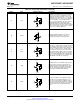
2.4 Ball Descriptions and Equivalent Circuits
Table 2-1. Analog Front-End and Clock Balls
Ball No. Name Equivalent Circuit Description
Differential signal I- and Q-inputs. In the Non-Dual
Edge Sampling (Non-DES) Mode, each I- and Q-
input is sampled and converted by its respective
channel with each positive transition of the CLK
input. In Non-ECM (Non-Extended Control Mode)
and DES Mode, both channels sample the I-input.
In Extended Control Mode (ECM), the Q-input
may optionally be selected for conversion in DES
Mode by the DEQ Bit (Addr: 0h, Bit 6).
Each I- and Q-channel input has an internal
common mode bias that is disabled when DC-
H1/J1 VinI+/- coupled Mode is selected. Both inputs must be
N1/M1 VinQ+/- either AC- or DC-coupled. The coupling mode is
selected by the V
CMO
Pin.
In Non-ECM, the full-scale range of these inputs is
determined by the FSR Pin; both I- and Q-
channels have the same full-scale input range. In
ECM, the full-scale input range of the I- and Q-
channel inputs may be independently set via the
Control Register (Addr: 3h and Addr: Bh). Note
that the high and low full-scale input range setting
in Non-ECM corresponds to the mid and minimum
full-scale input range in ECM.
The input offset may also be adjusted in ECM.
Differential Converter Sampling Clock. In the Non-
DES Mode, the analog inputs are sampled on the
positive transitions of this clock signal. In the DES
U2/V1 CLK+/-
Mode, the selected input is sampled on both
transitions of this clock. This clock must be AC-
coupled.
Differential DCLK Reset. A positive pulse on this
input is used to reset the DCLKI and DCLKQ
outputs of two or more ADC12D1600/1000RFs in
order to synchronize them with other
ADC12D1600/1000RFs in the system. DCLKI and
DCLKQ are always in phase with each other,
V2/W1 DCLK_RST+/-
unless one channel is powered down, and do not
require a pulse from DCLK_RST to become
synchronized. The pulse applied here must meet
timing relationships with respect to the CLK input.
Although supported, this feature has been
superseded by AutoSync.
6 Device Information Copyright © 2011–2013, Texas Instruments Incorporated
Submit Documentation Feedback
Product Folder Links: ADC12D1000RF ADC12D1600RF