
Specifications

ADC12D1000RF, ADC12D1600RF
SNAS519G –JULY 2011–REVISED APRIL 2013
www.ti.com
1000 0000 0000 22.5
1111 1111 1111 45
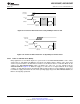
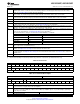
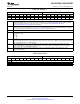
Table 6-18. I-channel Full Scale Range Adjust
Addr: 3h (0011b) POR state: 4000h
Bit 15 14 13 12 11 10 9 8 7 6 5 4 3 2 1 0
Name Res FM(14:0)
POR 0 1 0 0 0 0 0 0 0 0 0 0 0 0 0 0
Bit 15 Reserved. Must be set to 0b.
Bits 14:0 FM(14:0): FSR Magnitude. These bits increase the ADC full-scale range magnitude (straight binary coding.) The range is from
600 mV (0d) to 1000 mV (32767d) with the default setting at 800 mV (16384d). Monotonicity is specified by design only for the
9 MSBs. The mid-range (low) setting in ECM corresponds to the nominal (low) setting in Non-ECM. A greater range of FSR
values is available in ECM, i.e. FSR values above 800 mV. See V
IN_FSR
in Converter Electrical Characteristics Analog
Input/Output and Reference Characteristics for characterization details.
Code FSR [mV]
000 0000 0000 0000 600
100 0000 0000 0000 (default) 800
111 1111 1111 1111 1000
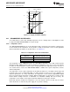
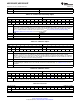
Table 6-19. Calibration Adjust
Addr: 4h (0100b) POR state: DB4Bh
Bit 15 14 13 12 11 10 9 8 7 6 5 4 3 2 1 0
Name Res CSS Res SSC Res
POR 1 1 0 1 1 0 1 1 0 1 0 0 1 0 1 1
Bit 15 Reserved. Must be set as shown.
Bit 14 CSS: Calibration Sequence Select. The default 1b selects the following calibration sequence: reset all previously calibrated
elements to nominal values, do R
IN
Calibration, do internal linearity Calibration. Setting CSS = 0b selects the following
calibration sequence: do not reset R
IN
to its nominal value, skip R
IN
calibration, do internal linearity Calibration. The calibration
must be completed at least one time with CSS = 1b to calibrate R
IN
. Subsequent calibrations may be run with CSS = 0b (skip
R
IN
calibration) or 1b (full R
IN
and internal linearity Calibration).
Bits 13:8 Reserved. Must be set as shown.
Bit 7 SSC: SPI Scan Control. Setting this control bit to 1b allows the calibration values, stored in Addr: 5h, to be read/written. When
not reading/writing the calibration values, this control bit should left at its default 0b setting. See Calibration Feature for more
information.
Bits 6:0 Reserved. Must be set as shown.
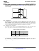
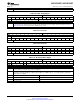
Table 6-20. Calibration Values
Addr: 5h (0101b) POR state: XXXXh
Bit 15 14 13 12 11 10 9 8 7 6 5 4 3 2 1 0
Name SS(15:0)
POR X X X X X X X X X X X X X X X X
Bits 15:0 SS(15:0): SPI Scan. When the ADC performs a self-calibration, the values for the calibration are stored in this register and may
be read from/ written to it. Set SSC (Addr: 4h, Bit 7) to read/write. See Calibration Feature for more information.
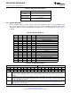
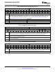
Table 6-21. Reserved
Addr: 6h (0110b) POR state: 1C2Eh
Bit 15 14 13 12 11 10 9 8 7 6 5 4 3 2 1 0
Name Res
POR 0 0 0 1 1 1 0 0 0 0 1 0 1 1 1 0
66 Functional Description Copyright © 2011–2013, Texas Instruments Incorporated
Submit Documentation Feedback
Product Folder Links: ADC12D1000RF ADC12D1600RF