
Specifications


GND
V
A
GND
V
A
V
A
A GND
-
+
100:100:
V
A
AGND
V
A
AGND
100
V
BIAS
50k
50k
ADC12D1000RF, ADC12D1600RF
SNAS519G –JULY 2011–REVISED APRIL 2013
www.ti.com
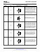
Table 2-1. Analog Front-End and Clock Balls (continued)
Ball No. Name Equivalent Circuit Description
Reference Clock Input. When the AutoSync
feature is active, and the ADC12D1600/1000RF is
in Slave Mode, the internal divided clocks are
Y4/W5 RCLK+/- synchronized with respect to this input clock. The
delay on this clock may be adjusted when
synchronizing multiple ADCs. This feature is
available in ECM via Control Register (Addr: Eh).
Reference Clock Output 1 and 2. These signals
provide a reference clock at a rate of CLK/4, when
enabled, independently of whether the ADC is in
Master or Slave Mode. They are used to drive the
RCLK of another ADC12D1600/1000RF, to enable
automatic synchronization for multiple ADCs
Y5/U6 RCOut1+/-
(AutoSync feature). The impedance of each trace
V6/V7 RCOut2+/-
from RCOut1 and RCOut2 to the RCLK of another
ADC12D1600/1000RF should be 100Ω
differential. Having two clock outputs allows the
auto-synchronization to propagate as a binary
tree. Use the DOC Bit (Addr: Eh, Bit 1) to enable/
disable this feature; default is disabled.
Table 2-2. Control and Status Balls
Ball No. Name Equivalent Circuit Description
Dual Edge Sampling (DES) Mode select. In the
Non-Extended Control Mode (Non-ECM), when
this input is set to logic-high, the DES Mode of
operation is selected, meaning that the VinI input
is sampled by both channels in a time-interleaved
manner. The VinQ input is ignored. When this
V5 DES input is set to logic-low, the device is in Non-DES
Mode, i.e. the I- and Q-channels operate
independently. In the Extended Control Mode
(ECM), this input is ignored and DES Mode
selection is controlled through the Control Register
by the DES Bit (Addr: 0h, Bit 7); default is Non-
DES Mode operation.
Calibration Delay select. By setting this input logic-
high or logic-low, the user can select the device to
wait a longer or shorter amount of time,
V4 CalDly respectively, before the automatic power-on self-
calibration is initiated. This feature is pin-controlled
only and is always active during ECM and Non-
ECM.
8 Device Information Copyright © 2011–2013, Texas Instruments Incorporated
Submit Documentation Feedback
Product Folder Links: ADC12D1000RF ADC12D1600RF