ADCP-75-169 Issue 1 June 2004 Digivance® LRCS System Rear Access Host Unit Installation and Maintenance Manual 19717-A 1284820 Rev A
ADCP-75-169 • Issue 1 • June 2004 • Preface COPYRIGHT © 2004, ADC Telecommunications, Inc. All Rights Reserved Printed in the U.S.A. REVISION HISTORY ISSUE DATE 1 06/2004 REASON FOR CHANGE Original release. LIST OF CHANGES The technical changes incorporated into this issue are listed below. PAGE IDENTIFIER All DESCRIPTION OF CHANGE Original release TRADEMARK INFORMATION ADC, Digivance, PowerWorx, and FiberGuide are registered trademarks of ADC Telecommunications, Inc.
ADCP-75-169 • Issue 1 • June 2004 • Preface TABLE OF CONTENTS Content Page ABOUT THIS MANUAL . . . . . . . . . . . . . . . . . . . . . . . . . . . . . . . . . . . . . . . . . . . . . . . . . . . . . . . . . . . . . . . . . . . . . . . . . v Related Publications . . . . . . . . . . . . . . . . . . . . . . . . . . . . . . . . . . . . . . . . . . . . . . . . . . . . . . . . . . . . . . . . . . . . . . . . . . v ADMONISHMENTS . . . . . . . . . . . . . . . . . . . . . . . . . . . . . . . . . . . . . . . . . .
ADCP-75-169 • Issue 1 • June 2004 • Preface TABLE OF CONTENTS Content Page Blank Page iv © 2004, ADC Telecommunications, Inc.
ADCP-75-169 • Issue 1 • June 2004 • Preface ABOUT THIS MANUAL This publication provides a basic description of the Digivance LRCS rear access Host Unit (HU) plus the installation and maintenance procedures. Also described are various accessories that may be used with the HU.
ADCP-75-169 • Issue A • June 2001 • Preface GENERAL SAFETY PRECAUTIONS Warning: Wet conditions increase the potential for receiving an electrical shock when installing or using electrically-powered equipment. To prevent electrical shock, never install or use electrical equipment in a wet location or during a lightning storm. STANDARDS CERTIFICATION FCC: This equipment complies with the applicable sections of Title 47 CFR Part 90 (SMR).
ADCP-75-169 • Issue 1 • June 2004 • Preface LED LPA LRCS MHz MPE MTBF NEM NEMA NO NOC OSP PA REV RF RMA RU SMR STM UL VDC VSWR WECO WDM Light Emitting Diode Linear Power Amplifier Long-Range Coverage Solution Mega Hertz Maximum Permissible Exposure Mean Time Between Failure Network Element Manager National Electrical Manufacturers Association Normally Open Network Operations Center Outside Plant Power Amplifier Reverse Radio Frequency Return Material Authorization Remote Unit Specialized Mobile Radio Spec
ADCP-75-169 • Issue A • June 2001 • Preface Blank Page viii © 2004, ADC Telecommunications, Inc.
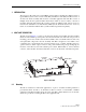
ADCP-75-169 • Issue 1 • June 2004 1 INTRODUCTION The rear access Host Unit serves as the EBTS servicing unit for the Digivance LRCS system. A typical LRCS system consists of a Host Unit (HU) and a Remote Unit (RU). The HU consists of an electronic chassis assembly that mounts in a standard equipment rack. The RU consists of multiple electronic and optical modules that mount in either an outdoor cabinet or an indoor mounting shelf. The HU and the RU together comprise an LRCS system.
ADCP-75-169 • Issue 1 • June 2004 2.2 RF Signal Connections The RF signal connections between the HU and the EBTS are supported through either two (non-diversity unit) or three (diversity unit) N-type female connectors. On non-diversity units, one connector is used for the forward path RF signal. The other connector is used for the reverse path RF signal. On diversity units, a third connector is used for the diversity path RF signal.
ADCP-75-169 • Issue 1 • June 2004 FRONT VIEW (1) DC POWER ON/OFF SWITCH (12) REVERSE 1 (13) REVERSE 2 RF OUT RF OUT (REFERENCE ITEMS 2 - 8) LED INDICATORS (14) FORWARD RF IN (9) SERVICE (10) NET IN (11) NET OUT INTERFACE CONNECTOR CONNECTOR CONNECTOR (15) DC POWER TERMINAL STRIP (16) COVER PLATE 19722-A REAR VIEW (17) ALARM OUTPUT CONNECTOR (18) PORT 1 (19) PORT 2 (20) PORT 3 (21) GROUNDING STUD Figure 2. Host Unit User Interface Table 1.
ADCP-75-169 • Issue 1 • June 2004 Table 1. Host Unit User Interface, continued REF NO USER INTERFACE DESIGNATION DEVICE FUNCTIONAL DESCRIPTION 7 PORT 1/PORT 2 Multi-colored LED (green/red) Indicates if the reverse/forward path optical signals from the STM/HU are normal (green), if no signals are detected (red), or if excessive errors are detected (red). See Note.
ADCP-75-169 • Issue 1 • June 2004 3 HOST UNIT ACCESSORIES This section provides a brief description of various accessory items that are available separately. The accessory items may or may not be required depending on the application. 3.1 Interface Panels The interface panels are accessory items that are used when multiple EBTS’s require connection to a single HU. Two types of panels are available: the Primary Interface Panel and the Expansion Panel.
ADCP-75-169 • Issue 1 • June 2004 18824-A Figure 4. Expansion Panel 3.2 Wavelength Division Multiplexer System The Wavelength Division Multiplexer (WDM) system is an accessory product that is used when it is desirable or necessary to combine the forward and reverse path optical signals from one Digivance system onto a single optical fiber. Each WDM system consists of a host module and a remote module. The HU provides a mounting slot for installing a WDM host module.
ADCP-75-169 • Issue 1 • June 2004 3.3 Coarse Wavelength Division Multiplexer System The Coarse Wavelength Division Multiplexer (CWDM) system is an accessory product that is used when it is desirable or necessary to combine the forward and reserve path optical signals from up to four Digivance systems onto a single optical fiber. Each CWDM system consists of a Host Module, Host Module mounting shelf, and Remote Module. The CWDM Host Module mounting shelf can support up to three CWDM Host Modules.
ADCP-75-169 • Issue 1 • June 2004 4 INSTALLATION PROCEDURES This section provides the installation procedures for the HU and the WDM host module (accessory item). The installation procedures for the Interface Panels are provided in the Digivance Long Range Coverage Solution SMR Interface Panels User Manual (ADCP-75-143).
ADCP-75-169 • Issue 1 • June 2004 4.2 Unpacking and Inspection This section provides instructions for opening the shipping boxes, verifying that all parts have been received, and verifying that no shipping damage has occurred. Use the following procedure to unpack and inspect the HU and any accessories: 1. Open the shipping cartons and carefully unpack each component from the protective packing material. 2. Check each component for broken or missing parts.
ADCP-75-169 • Issue 1 • June 2004 When routed to the RU outdoor cabinet, the OSP fiber optic cable should be spliced to a connectorized outdoor-rated cable (consisting of individual jacketed pigtails) which is then routed into the outdoor cabinet. The individual pigtails can then be connected directly to the STM optical ports. A connector is provided on the bottom of the RU outdoor cabinet to seal the cable entry point and provide strain relief.
ADCP-75-169 • Issue 1 • June 2004 FOR INSTALLATION IN 23-INCH RACKS, REMOVE AND REINSTALL MOUNTING BRACKETS AS SHOWN 17864-A Figure 9. Installing the Mounting Brackets for 23-Inch Rack Installations 4. Position the HU in the designated mounting space in the rack (per system design plan) and then secure (but do not tighten) the HU to the rack using the four machine screws provided (use #12-24 or M6 x 10 screws, whichever is appropriate) as shown in Figure 10.
ADCP-75-169 • Issue 1 • June 2004 4.5 Chassis Ground Connection A stud is provided on the rear side of the chassis for connecting a grounding wire to the chassis. Use the following procedure to connect the grounding wire to the chassis and to route the grounding wire to an approved earth ground source. 1. Obtain a length of #18 AWG (1.00 mm) insulated stranded copper wire for use as a chassis grounding wire. 2. Terminate one end of the wire with a ring terminal. 3.
ADCP-75-169 • Issue 1 • June 2004 and –40 dBm. Refer to the applicable System Operation and Maintenance Manual for the procedure to determine the forward path input signal level. If the Primary Interface Panel and Expansion Panel are required, refer to the Digivance LRCS SMR Interface Panels User Manual (ADCP-75-143) for the coaxial cable installation procedures. The HU should be mounted as close as possible to the EBTS to minimize cable losses.
ADCP-75-169 • Issue 1 • June 2004 7. If the HU supports diversity, connect the diversity reverse path cable to the REVERSE 2 RF OUT connector on the HU front panel (see Figure 12). 8. Dress and secure cables at the HU. 9. Complete all remaining coaxial connections as specified in the system design plan. 4.7 WDM Mounting Procedure (Accessory) A bi-directional wavelength division multiplexer (WDM) module is available as an accessory item for the Digivance system.
ADCP-75-169 • Issue 1 • June 2004 path (uplink) signal. The PORT 3 port provides the optical connection for the diversity reverse path (uplink) signal. The optical connections are dependent on whether or not a WDM host module (accessory) or CWDM host module (accessory) is installed: • If the installation does not include either a WDM or CWDM module, proceed to Section 4.8.1 for the optical connections procedure. • If the installation includes a WDM module, proceed to Section 4.8.
ADCP-75-169 • Issue 1 • June 2004 PORT 1 FORWARD PATH PORT 2 REVERSE PATH 19721-A PORT 3 DIVERSITY REVERSE PATH Figure 14. Fiber Optic Cable Connections To Host Unit 6. Route the patch cords from the HU to the fiber distribution panel. Note: The HU optical adapters are angled to the left. Therefore, always route patch cords to the HU from the left side of the rack. Routing patch cords to the HU from the right may exceed the bend radius limitations for the optical fiber. 7.
ADCP-75-169 • Issue 1 • June 2004 3. Clean the patch cord connector (follow patch cord supplier’s recommendations). Note: To protect the optical receivers, insert a 15 dB attenuator in each optical path. After the optical power has been measured, the attenuator may be resized or removed. 4. Insert the connector into one of the WDM module’s optical port (port 1). 5. Route the patch cord from the WDM to the fiber distribution panel. 6.
ADCP-75-169 • Issue 1 • June 2004 4.9 Controller Area Network Connections Controller area Network (CAN) interface connections between multiple HU’s are supported by a pair of RJ-45 jacks. One of the jacks is designated as the NET IN port and the other jack is designated as the NET OUT port. The CAN interface allows up to 24 HU’s to be connected together (in daisy-chain fashion) and controlled through a single Digivance EMS computer. A one meter long cable is available (accessory) for CAN connections.
ADCP-75-169 • Issue 1 • June 2004 HOST UNIT 1 NET IN NET OUT HOST UNIT 2 HOST UNIT 3 NET IN NET OUT NET IN NET OUT 16900-B TO NEXT HOST UNIT (NOTE: LAST HOST HAS NO CONNECTION AT NET OUT) CONTROLLER AREA NETWORK INTERFACE CABLES Figure 17. Configuring CAN Connections with Multiple Host Units 4.10 EMS Computer Connection The service interface connection between the HU and the EMS computer is supported by a single DB-9 female connector. The service connector provides an RS-232 DTE interface.
ADCP-75-169 • Issue 1 • June 2004 4.11 External Alarm System Connections The alarm interface between the HU and an external alarm system is supported by a six-terminal plug (with screw-type terminals) that connects to a receptacle mounted on the HU front panel. The terminal plug provides connections to normally open (NO) and normally closed (NC) dry type alarm contacts for both major and minor alarms. A category 3 or 5 cable is typically used to connect the HU to the external alarm system.
ADCP-75-169 • Issue 1 • June 2004 6. Connect the Major and Minor alarm wire pairs to the appropriate terminals on the external alarm system. 7. Dress and secure cable per standard industry practice. 4.12 DC Power Connections The HU is powered by ± 21 to 60 VDC power (nominal ± 24 or ± 48 VDC). The power is fed to the HU through a screw-down type terminal strip located on the rear side of the unit.
ADCP-75-169 • Issue 1 • June 2004 6. Connect the power wires to the appropriate terminals as specified in the fuse panel user manual. Note: When connecting the equipment to the supply circuit, be sure to check equipment nameplate ratings to avoid overloading circuits which may cause damage to over-current protection devices and supply wiring. 7. Dress and secure the power wiring at the fuse panel and the HU.
ADCP-75-169 • Issue 1 • June 2004 17873-A Figure 21. Host Unit Fan/Grill Assembly Removal 6. Lift the small latch on each wiring harness connector and carefully unplug each connector from the circuit board connector. 7. Remove the plastic rivets that secure each fan to the grill by pushing outward on the rivet center post until the rivet can be withdrawn from the grill as shown in Figure 22. 16173-B Figure 22. Removing Host Unit Fans From Grill 8. Remove both fans from the grill 9.
ADCP-75-169 • Issue 1 • June 2004 6 CUSTOMER INFORMATION AND ASSISTANCE PHONE: EUROPE Sales Administration: +32-2-712-65 00 Technical Assistance: +32-2-712-65 42 EUROPEAN TOLL FREE NUMBERS Germany: 0180 2232923 UK: 0800 960236 Spain: 900 983291 France: 0800 914032 Italy: 0800 782374 U.S.A.