
Specifications

ADC12D1800RF
www.ti.com
SNAS518I –JULY 2011–REVISED JANUARY 2014
6.3.3.3 Power-on Calibration
For standard operation, power-on calibration begins after a time delay following the application of power,
as determined by the setting of the CalDly Pin and measured by t
CalDly
(see Converter Electrical
Characteristics Calibration). This delay allows the power supply to come up and stabilize before the
power-on calibration takes place. The best setting (short or long) of the CalDly Pin depends upon the
settling time of the power supply.
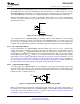
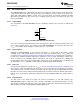
It is strongly recommended to set CalDly Pin (to either logic-high or logic-low) before powering the device
on since this pin affects the power-on calibration timing. This may be accomplished by setting CalDly via
an external 1kΩ resistor connected to GND or V
A
. If the CalDly Pin is toggled while the device is powered-
on, it can execute a calibration even though the CAL Pin / Bit remains logic-low.
The power-on calibration will be not be performed if the CAL pin is logic-high at power-on. In this case, the
calibration cycle will not begin until the on-command calibration conditions are met. The ADC12D1800RF
will function with the CAL pin held high at power up, but no calibration will be done and performance will
be impaired.
If it is necessary to toggle the CalDly Pin during the system power up sequence, then the CAL Pin / Bit
must be set to logic-high before the toggling and afterwards for 10
9
Sampling Clock cycles. This will
prevent the power-on calibration, so an on-command calibration must be executed or the performance will
be impaired.
6.3.3.4 On-command Calibration
In addition to the power-on calibration, it is recommended to execute an on-command calibration
whenever the settings or conditions to the device are altered significantly, in order to obtain optimal
parametric performance. Some examples include: changing the FSR via ECM, power-cycling either
channel, and switching into or out of DES Mode. For best performance, it is also recommended that an
on-command calibration be run 20 seconds or more after application of power and whenever the operating
temperature changes significantly, relative to the specific system performance requirements.
Due to the nature of the calibration feature, it is recommended to avoid unnecessary activities on the
device while the calibration is taking place. For example, do not read or write to the Serial Interface or use
the DCLK Reset feature while calibrating the ADC. Doing so will impair the performance of the device until
it is re-calibrated correctly. Also, it is recommended to not apply a strong narrow-band signal to the analog
inputs during calibration because this may impair the accuracy of the calibration; broad spectrum noise is
acceptable.
6.3.3.5 Calibration Adjust
The sequence of the calibration event itself may be adjusted. This feature can be used if a shorter
calibration time than the default is required; see t
CAL
in Converter Electrical Characteristics Calibration.
However, the performance of the device, when using this feature is not ensured.
The calibration sequence may be adjusted via CSS (Addr: 4h, Bit 14). The default setting of CSS = 1b
executes both R
IN
and R
IN_CLK
Calibration (using Rtrim) and internal linearity Calibration (using Rext).
Executing a calibration with CSS = 0b executes only the internal linearity Calibration. The first time that
Calibration is executed, it must be with CSS = 1b to trim R
IN
and R
IN_CLK
. However, once the device is at
its operating temperature and R
IN
has been trimmed at least one time, it will not drift significantly. To save
time in subsequent calibrations, trimming R
IN
and R
IN_CLK
may be skipped, i.e. by setting CSS = 0b.
Copyright © 2011–2014, Texas Instruments Incorporated Functional Description 53
Submit Documentation Feedback
Product Folder Links: ADC12D1800RF