
Specifications

ADC12D1800RF
SNAS518I –JULY 2011–REVISED JANUARY 2014
www.ti.com
6.3.3.6 Read / Write Calibration Settings
When the ADC performs a calibration, the calibration constants are stored in an array which is accessible
via the Calibration Values register (Addr: 5h). To save the time which it takes to execute a calibration, t
CAL
,
or to allow for re-use of a previous calibration result, these values can be read from and written to the
register at a later time. For example, if an application requires the same input impedance, R
IN
, this feature
can be used to load a previously determined set of values. For the calibration values to be valid, the ADC
must be operating under the same conditions, including temperature, at which the calibration values were
originally determined by the ADC.
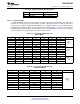
To read calibration values from the SPI, do the following:
1. Set ADC to desired operating conditions.
2. Set SSC (Addr: 4h, Bit 7) to 1.
3. Read exactly 240 times the Calibration Values register (Addr: 5h). The register values are R0, R1, R2...
R239 where R0 is a dummy value. The contents of R<239:1> should be stored.
4. Set SSC (Addr: 4h, Bit 7) to 0.
5. Continue with normal operation.
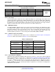
To write calibration values to the SPI, do the following:
1. Set ADC to operating conditions at which Calibration Values were previously read.
2. Set SSC (Addr: 4h, Bit 7) to 1.
3. Write exactly 239 times the Calibration Values register (Addr: 5h). The registers should be written R1,
R2, ... , R239.
4. Make two additional dummy writes of 0000h.
5. Set SSC (Addr: 4h, Bit 7) to 0.
6. Continue with normal operation.
6.3.3.7 Calibration and Power-Down
If PDI and PDQ are simultaneously asserted during a calibration cycle, the ADC12D1800RF will
immediately power down. The calibration cycle will continue when either or both channels are powered
back up, but the calibration will be compromised due to the incomplete settling of bias currents directly
after power up. Therefore, a new calibration should be executed upon powering the ADC12D1800RF back
up. In general, the ADC12D1800RF should be recalibrated when either or both channels are powered
back up, or after one channel is powered down. For best results, this should be done after the device has
stabilized to its operating temperature.
6.3.3.8 Calibration and the Digital Outputs
During calibration, the digital outputs (including DI, DId, DQ, DQd and OR) are set logic-low, to reduce
noise. The DCLK runs continuously during calibration. After the calibration is completed and the CalRun
signal is logic-low, it takes an additional 60 Sampling Clock cycles before the output of the
ADC12D1800RF is valid converted data from the analog inputs. This is the time it takes for the pipeline to
flush, as well as for other internal processes.
6.3.4 Power Down
On the ADC12D1800RF, the I- and Q-channels may be powered down individually. This may be
accomplished via the control pins, PDI and PDQ, or via ECM. In ECM, the PDI and PDQ pins are logically
OR'd with the Control Register setting. See Power Down I-channel Pin (PDI) and Power Down Q-channel
Pin (PDQ) for more information.
54 Functional Description Copyright © 2011–2014, Texas Instruments Incorporated
Submit Documentation Feedback
Product Folder Links: ADC12D1800RF