
Specifications

ADC12D1800RF
www.ti.com
SNAS518I –JULY 2011–REVISED JANUARY 2014
6.4.2.5 CLK Jitter
High speed, high performance ADCs such as the ADC12D1800RF require a very stable input clock signal
with minimum phase noise or jitter. ADC jitter requirements are defined by the ADC resolution (number of
bits), maximum ADC input frequency and the input signal amplitude relative to the ADC input full scale
range. The maximum jitter (the sum of the jitter from all sources) allowed to prevent a jitter-induced
reduction in SNR is found to be
t
J(MAX)
= ( V
IN(P-P)
/ V
FSR
) x (1/(2
(N+1)
x π x f
IN
)) (3)
where t
J(MAX)
is the rms total of all jitter sources in seconds, V
IN(P-P)
is the peak-to-peak analog input signal,
V
FSR
is the full-scale range of the ADC, "N" is the ADC resolution in bits and f
IN
is the maximum input
frequency, in Hertz, at the ADC analog input.
t
J(MAX)
is the square root of the sum of the squares (RSS) sum of the jitter from all sources, including: the
ADC input clock, system, input signals and the ADC itself. Since the effective jitter added by the ADC is
beyond user control, it is recommended to keep the sum of all other externally added jitter to a minimum.
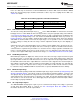
6.4.2.6 CLK Layout
The ADC12D1800RF clock input is internally terminated with a trimmed 100Ω resistor. The differential
input clock line pair should have a characteristic impedance of 100Ω and (when using a balun), be
terminated at the clock source in that (100Ω) characteristic impedance.
It is good practice to keep the ADC input clock line as short as possible, tightly coupled, keep it well away
from any other signals, and treat it as a transmission line. Otherwise, other signals can introduce jitter into
the input clock signal. Also, the clock signal can introduce noise into the analog path if it is not properly
isolated.
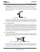
6.4.3 THE LVDS OUTPUTS
The Data, ORI, ORQ, DCLKI and DCLKQ outputs are LVDS. The electrical specifications of the LVDS
outputs are compatible with typical LVDS receivers available on ASIC and FPGA chips; but they are not
IEEE or ANSI communications standards compliant due to the low +1.9V supply used on this chip. These
outputs should be terminated with a 100Ω differential resistor placed as closely to the receiver as possible.
If the 100Ω differential resistor is built in to the receiver, then an externally placed resistor is not
necessary. This section covers common-mode and differential voltage, and data rate.
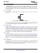
6.4.3.1 Common-mode and Differential Voltage
The LVDS outputs have selectable common-mode and differential voltage, V
OS
and V
OD
; see Converter
Electrical Characteristics Digital Control and Output Pin Characteristics. See Output Control and Adjust for
more information.
Selecting the higher V
OS
will also increase V
OD
slightly. The differential voltage, V
OD
, may be selected for
the higher or lower value. For short LVDS lines and low noise systems, satisfactory performance may be
realized with the lower V
OD
. This will also result in lower power consumption. If the LVDS lines are long
and/or the system in which the ADC12D1800RF is used is noisy, it may be necessary to select the higher
V
OD
.
6.4.3.2 Output Data Rate
The data is produced at the output at the same rate it is sampled at the input. The minimum
recommended input clock rate for this device is f
CLK(MIN)
; see Converter Electrical Characteristics AC
Electrical Characteristics. However, it is possible to operate the device in 1:2 Demux Mode and capture
data from just one 12-bit bus, e.g. just DI (or DId) although both DI and DId are fully operational. This will
decimate the data by two and effectively halve the data rate.
Copyright © 2011–2014, Texas Instruments Incorporated Functional Description 59
Submit Documentation Feedback
Product Folder Links: ADC12D1800RF