
Specifications

ADC12D1800RF
SNAS518I –JULY 2011–REVISED JANUARY 2014
www.ti.com
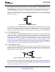
6.4.3.3 Terminating Unused LVDS Output Pins
If the ADC is used in Non-Demux Mode, then only the DI and DQ data outputs will have valid data present
on them. The DId and DQd data outputs may be left not connected; if unused, they are internally at TRI-
STATE.
Similarly, if the Q-channel is powered-down (i.e. PDQ is logic-high), the DQ data output pins, DCLKQ and
ORQ may be left not connected.
6.4.4 SYNCHRONIZING MULTIPLE ADC12D1800RFS IN A SYSTEM
The ADC12D1800RF has two features to assist the user with synchronizing multiple ADCs in a system;
AutoSync and DCLK Reset. The AutoSync feature and designates one ADC12D1800RF as the Master
ADC and other ADC12D1800RFs in the system as Slave ADCs. The DCLK Reset feature performs the
same function as the AutoSync feature, but is the first generation solution to synchronizing multiple ADCs
in a system; it is disabled by default. For the application in which there are multiple Master and Slave
ADC12D1800RFs in a system, AutoSync may be used to synchronize the Slave ADC12D1800RF(s) to
each respective Master ADC12D1800RF and the DCLK Reset may be used to synchronize the Master
ADC12D1800RFs to each other.
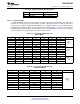
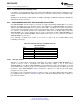
If the AutoSync or DCLK Reset feature is not used, see Table 6-10 for recommendations about
terminating unused pins.
Table 6-10. Unused AutoSync and DCLK Reset Pin
Recommendation
Pin(s) Unused termination
RCLK+/- Do not connect.
RCOUT1+/- Do not connect.
RCOUT2+/- Do not connect.
DCLK_RST+ Connect to GND via 1kΩ resistor.
DCLK_RST- Connect to V
A
via 1kΩ resistor.
6.4.4.1 AutoSync Feature
AutoSync is a feature which continuously synchronizes the outputs of multiple ADC12D1800RFs in a
system. It may be used to synchronize the DCLK and data outputs of one or more Slave
ADC12D1800RFs to one Master ADC12D1800RF. Several advantages of this feature include: no special
synchronization pulse required, any upset in synchronization is recovered upon the next DCLK cycle, and
the Master / Slave ADC12D1800RFs may be arranged as a binary tree so that any upset will quickly
propagate out of the system.
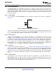
An example system is shown below in Figure 6-9 which consists of one Master ADC and two Slave ADCs.
For simplicity, only one DCLK is shown; in reality, there is DCLKI and DCLKQ, but they are always in
phase with one another.
60 Functional Description Copyright © 2011–2014, Texas Instruments Incorporated
Submit Documentation Feedback
Product Folder Links: ADC12D1800RF