
Specifications


Cross Section Line
IC Die
Not to Scale
Mold Compound
Copper Heat Slug
Substrate
4
JC_2
4
JC_1
1.9V ADC Main
Switching
Regulator
Linear
Regulator
V
DR
V
E
V
A
V
TC
HV or Unreg
Voltage
Intermediate
Voltage
ADC
Dielectric 1
Dielectric 2
Dielectric 3
Dielectric 4
Dielectric 5
Dielectric 6
Dielectric 7
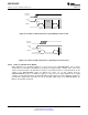
Top Layer ± Signal 1
Ground 1
Signal 2
Ground 2
Power 1
Ground 3
Bottom Layer ± Signal X
Signal 3
Cross Section
Line
ADC12D1800RF
www.ti.com
SNAS518I –JULY 2011–REVISED JANUARY 2014
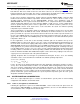
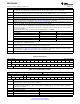
Figure 6-10. Power and Grounding Example
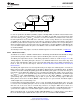
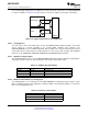
6.4.5.5 Thermal Management
The Heat Slug Ball Grid Array (HSBGA) package is a modified version of the industry standard plastic
BGA (Ball Grid Array) package. Inside the package, a copper heat spreader cap is attached to the
substrate top with exposed metal in the center top area of the package. This results in a 20%
improvement (typical) in thermal performance over the standard plastic BGA package.
Figure 6-11. HSBGA Conceptual Drawing
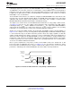
The center balls are connected to the bottom of the die by vias in the package substrate, Figure 6-11. This
gives a low thermal resistance between the die and these balls. Connecting these balls to the PCB ground
planes with a low thermal resistance path is the best way dissipate the heat from the ADC. These pins
should also be connected to the ground plane via a low impedance path for electrical purposes. The direct
connection to the ground planes is an easy method to spread heat away from the ADC. Along with the
ground plane, the parallel power planes will provide additional thermal dissipation.
Copyright © 2011–2014, Texas Instruments Incorporated Functional Description 63
Submit Documentation Feedback
Product Folder Links: ADC12D1800RF