
Specifications


ADC12D1800RF
SNAS518I –JULY 2011–REVISED JANUARY 2014
www.ti.com
Bit 11 PDI: Power-down I-channel. When this bit is set to 0b, the I-channel is fully operational; when it is set to 1b, the I-channel is
powered-down. The I-channel may be powered-down via this bit or the PDI Pin, which is active, even in ECM.
Bit 10 PDQ: Power-down Q-channel. When this bit is set to 0b, the Q-channel is fully operational; when it is set to 1b, the Q-channel
is powered-down. The Q-channel may be powered-down via this bit or the PDQ Pin, which is active, even in ECM.
Bit 9 Reserved. Must be set to 0b.
Bit 8 LFS: Low-Frequency Select. If the sampling clock (CLK) is at or below 300 MHz, set this bit to 1b for improved performance.
Bit 7 DES: Dual-Edge Sampling Mode select. When this bit is set to 0b, the device will operate in the Non-DES Mode; when it is set
to 1b, the device will operate in the DES Mode. See DES/Non-DES Mode for more information.
Bit 6 DEQ: DES Q-input select, a.k.a. DESQ Mode. When the device is in DES Mode, this bit selects the input that the device will
operate on. The default setting of 0b selects the I-input and 1b selects the Q-input.
Bit 5 DIQ: DES I- and Q-input, a.k.a. DESIQ Mode. When in DES Mode, setting this bit to 1b shorts the I- and Q-inputs internally to
the device. If the bit is left at its default 0b, the I- and Q-inputs remain electrically separate. To operate the device in DESIQ
Mode, Bits<7:5> must be set to 101b. In this mode, both the I- and Q-inputs must be externally driven; see DES/Non-DES
Mode for more information.
The allowed DES Modes settings are shown below: For DESCLKIQ Mode, see Addr Eh.
Mode Addr 0h, Bits<7:5> Addr Eh, Bit<6>
Non-DES Mode 000b 0b
DESI Mode 100b 0b
DESQ Mode 110b 0b
DESIQ Mode 101b 0b
DESCLKIQ Mode 000b 1b
Bit 4 2SC: Two's Complement output. For the default setting of 0b, the data is output in Offset Binary format; when set to 1b, the
data is output in Two's Complement format.
(2)
Bit 3 TSE: Time Stamp Enable. For the default setting of 0b, the Time Stamp feature is not enabled; when set to 1b, the feature is
enabled. See Output Control and Adjust for more information about this feature.
Bit 2 SDR: Single Data Rate. For the default setting of 0b, the data is clocked in Dual Data Rate; when set to 1b, the data is clocked
in Single Data Rate. See Output Control and Adjust for more information about this feature. Note that for Non-Demux Mode,
only 0° DDR Mode is available. See Table 6-5 for a selection of available modes.
Bits 1:0 Reserved. Must be set as shown.
(2) This pin / bit functionality is not tested in production test; performance is tested in the specified / default mode only.
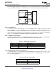
Table 6-16. Reserved
Addr: 1h (0001b) POR state: 2907h
Bit 15 14 13 12 11 10 9 8 7 6 5 4 3 2 1 0
Name Res
POR 0 0 1 0 1 0 0 1 0 0 0 0 0 1 1 1
Bits 15:0 Reserved. Must be set as shown.
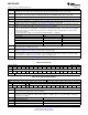
Table 6-17. I-channel Offset Adjust
Addr: 2h (0010b) POR state: 0000h
Bit 15 14 13 12 11 10 9 8 7 6 5 4 3 2 1 0
Name Res OS OM(11:0)
POR 0 0 0 0 0 0 0 0 0 0 0 0 0 0 0 0
Bits 15:13 Reserved. Must be set to 0b.
Bit 12 OS: Offset Sign. The default setting of 0b incurs a positive offset of a magnitude set by Bits 11:0 to the ADC output. Setting
this bet to 1b incurs a negative offset of the set magnitude.
Bits 11:0 OM(11:0): Offset Magnitude. These bits determine the magnitude of the offset set at the ADC output (straight binary coding).
The range is from 0 mV for OM(11:0) = 0d to 45 mV for OM(11:0) = 4095d in steps of ~11 µV. Monotonicity is specified by
design only for the 9 MSBs.
Code Offset [mV]
0000 0000 0000 (default) 0
1000 0000 0000 22.5
1111 1111 1111 45
70 Functional Description Copyright © 2011–2014, Texas Instruments Incorporated
Submit Documentation Feedback
Product Folder Links: ADC12D1800RF