
Telecommunications Power Distribution Panel User Manual 70

ADCP-80-524 • Issue 1 • November 2001
Page 11
© 2001, ADC Telecommunications, Inc.
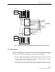
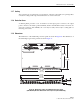
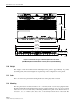
Figure 7. PowerWorx Type 70 Fuse Panel Block Diagram (Traditional Power Fuse Panel Shown)
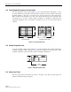
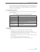
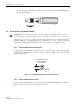
1.4 Input Connectors
Each bus is equipped with two (2) input connectors on the rear of the fuse panel through which
input power is applied. The two input power connectors are labeled BATT (battery) and RTN
(return) on the fuse panel. The following types of input connectors are available:
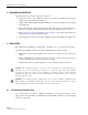
• Two-hole compression lug (stud type) connectors: Each connector consists of two studs
mounted on a plated copper bar and two nuts. Each set of studs can accept various size 2-
hole lugs which can be used with a number of wire sizes ranging from #14 to #2 AWG
copper wire. Various lugs are available as accessories.
•Setscrew barrel connectors: Each connector has two (2) barrels. On each connector, the
barrel that is closest to the outside of the fuse panel (barrel without a cap) is used to secure
1
2
3
4
5
6
7
8
BATTERY RETURN
BATTERY A
RETURN A
POWER A LED
FUSE
ALARM A LED
1
2
3
4
5
6
7
8
BATTERY RETURN
BATTERY B
RETURN B
BUS A
RETURN A
POWER B LED
FUSE
ALARM B LED
BUS B
RETURN B
–24V/–48V
–24V/–48V
C
NO
NC
C
NO
NC
SYSTEM ALARM
CONNECTIONS
16758-A