AD-115ES Installation Manual Phase 7 / Dual Timer / S.A.F.E. System WARNING: For your safety the information in this manual must be followed to minimize the risk of fire or explosion and to prevent property damage, personal injury or death. — Do not store or use gasoline or other flammable vapors and liquids in the vicinity of this or any other appliance.
Retain This Manual In A Safe Place For Future Reference American Dryer Corporation products embody advanced concepts in engineering, design, and safety. If this product is properly maintained, it will provide many years of efficient, trouble free and, most importantly, safe operation. ONLY qualified technicians should service this equipment. OBSERVE ALL SAFETY PRECAUTIONS displayed on the equipment or specified in the installation manual included with the dryer.
! WARNING ▲ Proposition 65 Use of this product could expose you to substances from fuel combustion that contain chemicals known to the State of California to cause cancer, birth defects and other reproductive harm.
WARNING The dryer must never be operated with any of the back guards, outer tops, or service panels removed. PERSONAL INJURY OR FIRE COULD RESULT. WARNING DRYER MUST NEVER BE OPERATED WITHOUT THE LINT FILTER/SCREEN IN PLACE, EVEN IF AN EXTERNAL LINT COLLECTION SYSTEM IS USED. IMPORTANT PLEASE OBSERVE ALL SAFETY PRECAUTIONS displayed on the equipment and/or specified in the installation manual included with the dryer.
Table of Contents SECTION I SAFETY PRECAUTIONS .............................................................................................................................. 2 SECTION II SPECIFICATIONS/COMPONENT IDENTIFICATION ......................................................................... 4 A. Specifications .......................................................................................................................................... 4 B. Component Identification ......................
SECTION I SAFETY PRECAUTIONS WARNING: For your safety, the information in this manual must be followed to minimize the risk of fire or explosion or to prevent property damage, personal injury, or loss of life. WARNING: The dryer must never be operated with any of the back guards, outer tops, or service panels removed. PERSONAL INJURY OR FIRE COULD RESULT. 1. DO NOT store or use gasoline or other flammable vapors and liquids in the vicinity of this or any other appliance. 2.
. A program should be established for the inspection and cleaning of lint in the heating unit area, exhaust ductwork, and inside the dryer. The frequency of inspection and cleaning can best be determined from experience at each location. WARNING: The collection of lint in the burner area and exhaust ductwork could create a fire hazard. 8. For personal safety, the dryer must be electrically grounded in accordance with local codes and/or the National Electrical Code ANSI/NFPA NO.
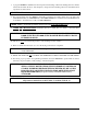
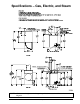
SECTION II SPECIFICATIONS/COMPONENT IDENTIFICATION A.
Specifications – Gas, Electric, and Steam NOTE: ADC reserves the right to make changes in specifications at any time without notice or obligation. 113202 - 10 www.amdry.
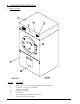
B. COMPONENT IDENTIFICATION 1. Dryer Front View Illus. No. 1 2 3 4 5 6 7 6 Description Microprocessor Control and Keypad Panel Assembly (controls) Control (top access) Door Assembly Main Door Assembly Lint Door Assembly Lint Drawer Wire Diagram (located behind control door) Top Console (module) Assembly American Dryer Corp.
2. Dryer Rear View Illus. No. 1 2 3 4 5 6* 7 8 * Description Basket (tumbler) Drive Motor Assembly Blower Motor Mount Assembly Impellor (fan/blower) Assembly Idler Bearing Mount Assembly Basket (tumbler) Bearing Mount Assembly Electric Service Relay Box Heating Unit Data Label and Installation Label Electric service connections are made in this box. 113202 - 10 www.amdry.
SECTION III INSTALLATION PROCEDURES Installation should be performed by competent technicians in accordance with local and state codes. In the absence of these codes, the installation must conform to applicable American National Standards: ANSI Z223.1LATEST EDITION (National Fuel Gas Code) or ANSI/NFPA NO. 70-LATEST EDITION (National Electrical Code) or in Canada, the installation must conform to applicable Canadian Standards: CAN/CGA-B149.1-M91 (Natural Gas) or CAN/CGA-B149.2-M91 (Liquid Propane [L.P.
IMPORTANT: Dryer must be installed in a location/environment in which the ambient temperature remains between 40° F (4.44° C) and 130° F (54.44° C). B. UNPACKING AND SETTING UP Remove protective shipping material (i.e., plastic wrap and optional shipping box) from dryer. IMPORTANT: Dryer must be transported and handled in an upright position at ALL times. The dryer can be moved to its final location while still attached to the skid or with the skid removed.
2. The V-belts are disconnected from the basket drive motor for shipping. Reconnect V-belts, using the following instructions, before starting the dryer. a. Remove hardware holding back (belt) guard and remove guard from dryer. b. Lay one (1) belt into motor sheave (pulley) groove and wind belt into corresponding groove of the idler pulley by rotating the idler pulley by hand.
4. Exhaust Transition Piece WARNING An exhaust duct transition piece is shipped inside of the dryer’s tumbler and MUST be installed on the dryer’s exhaust duct, with the hardware provided, BEFORE location venting is connected to the dryer. THIS EXHAUST DUCT TRANSITION PIECE MUST BE INSTALLED FIRST! Failure to observe this installation requirement may result in damage to the dryer, create a FIRE HAZARD and will VOID the manufacturer’s warranty.
C. DRYER ENCLOSURE REQUIREMENTS Even though a 12-inch (30.48 cm) clearance is acceptable, it is recommended that the rear of the dryer be positioned approximately 3 feet (0.91 meters) from the nearest obstruction (i.e., wall) for ease of installation, maintenance, and service. Bulkheads and partitions should be made from noncombustible materials. The clearance between the bulkhead header and the dryer must be a minimum of 4-inches (10.16 cm) and must not extend more than 4-inches (10.
Air supply (make-up air) must be given careful consideration to ensure proper performance of each dryer. An unrestricted source of air is necessary for each dryer. An airflow of 2,100 cfm (cubic feet per minute) (59.5 cmm [cubic meters per minute]) must be supplied to each dryer. As a general rule, an unrestricted air entrance from the outdoors (atmosphere) of a minimum of 3 square feet (0.28 square meters) is required for each dryer.
CAUTION: IMPROPERLY SIZED OR INSTALLED EXHAUST DUCTWORK COULD CREATE A FIRE HAZARD. NOTE: When a dryer is exhausted separately, it is recommended that a back draft damper be installed. NOTE: When dryers are exhausted into a multiple (common) exhaust line, each dryer must be supplied with a back draft damper. The exhaust ductwork should be laid out in such a way that the ductwork travels as directly as possible to the outdoors with as few turns as possible. Single or independent dryer venting is recommended.
Outside Ductwork Protection To protect the outside end of the horizontal ductwork from the weather, a 90° elbow bent downward should be installed where the exhaust exits the building. If the exhaust ductwork travels vertically up through the roof, it should be protected from the weather by using a 180° turn to point the opening downward. In either case, allow at least twice the diameter of the duct between the duct opening and the nearest obstruction.
IMPORTANT: For extended ductwork runs, the cross section area of the duct can only be increased to an extent. Maximum proportional ductwork runs cannot exceed 20 feet (6.09 meters) more than the original limitations of 20 feet (6.09 meters) with two (2) elbows. When the ductwork approaches the maximum limits as noted in this manual, a professional heating, ventilating, and air-conditioning (HVAC) firm should be consulted for proper venting information. 3.
If it is not feasible to provide separate exhaust ducts for each dryer, ducts from individual dryers may be channeled into a “common main duct.” The individual ducts should enter the bottom or side of the main duct at an angle not more than 45° in the direction of airflow and should be spaced at least 46-1/8” (117.16 cm) apart. The main duct should be tapered, with the diameter increasing before each individual 14-inch (35.56 cm) (minimum for gas, electric, or steam dryers) duct is added.
IMPORTANT: Failure to comply with these codes or ordinances, and the requirements stipulated in this manual, can result in personal injury or component failure. NOTE: Component failure due to improper installation will VOID THE WARRANTY. Each dryer should be connected to an independently protected branch circuit. The dryer must be connected with copper wire only. DO NOT use aluminum wire; it could create a fire hazard.
Reversing, 3ø Motor (Electric) ELECTRICAL SERVICE SPECIFICATIONS (PER DRYER) IMPORTANT: 208 VAC AND 240 VAC ARE NOT THE SAME. When ordering, specify exact voltage. NOTES: When fuses are used they must be dual element, time delay, current limiting, class RK1 or RK5 ONLY. Calculate/determine correct fuse value, by applying either local and/or National Electrical Codes to listed appliance amp draw data. Circuit breakers are thermal-magnetic (industrial) type ONLY.
WARNING: 208 VAC AND 230/240 VAC ARE NOT THE SAME. Any damage done to dryer components due to improper voltage connections will automatically VOID THE WARRANTY. IMPORTANT: 380, 400, and 416 volt dryers are built 4-wire only. Customer must contact the factory to special order 3-wire systems. NOTE: ADC reserves the right to make changes in specifications at any time without notice or obligation. 3.
b. Electric Models ONLY For electric models made to operate at 208 VAC, 230/240 VAC, the electrical input connection is made into the terminal block located at the upper rear area of the dryer. For electric models made to operate at 380 VAC, 416 VAC, 440 VAC, or 480 VAC, the electrical input connection is made to the oven relay located at the upper rear area of the dryer. Input connection wiring must be sized properly to handle the dryer’s current draw. This information is printed on the dryer’s data label.
IMPORTANT: Failure to isolate or disconnect the dryer from supply as noted can cause irreparable damage to the gas valve and will VOID THE WARRANTY. WARNING: FIRE OR EXPLOSION COULD RESULT DUE TO FAILURE OF ISOLATING OR DISCONNECTING THE GAS SUPPLY AS NOTED. 1. Gas Supply The gas dryer installation must meet the American National Standard...National Fuel Gas Code ANSI Z223.1-LATEST EDITION, or in Canada, the Canadian Installation Codes CAN/CGA-B149.1 M91 (Natural Gas) or CAN/CGA-B149.2-M91 (L.P.
1) Natural Gas Regulation is controlled by the dryer’s gas valve’s internal regulator. Incoming supply pressure must be consistent between a minimum of 6.0 inches (14.92 mb) and a maximum of 12.0 inches (29.9 mb) water column (W.C.) pressure. 2) Liquid Propane (L.P.) Gas Dryers made for use with L.P. gas have the gas valve’s internal pressure regulator blocked open so that the gas pressure must be regulated upstream of the dryer. The pressure measured at each gas valve pressure tap must be a consistent 10.
A 1/8” N.P.T. plugged tap, accessible for a test gauge connection, must be installed in the main gas supply line immediately upstream of each dryer. IMPORTANT: Pipe joint compounds that resist the action of natural and liquid propane (L.P.) gases must be used. IMPORTANT: Test ALL connections for leaks by brushing on a soapy water solution (liquid detergent works well).
H. STEAM INFORMATION It is your responsibility to have ALL steam plumbing connections made by a qualified professional to ensure that the installation is adequate and conforms to local and state regulations or codes. IMPORTANT: Failure to comply with the requirements stipulated in this manual can result in component failure, which will VOID THE WARRANTY.
d. Shutoff valves for each dryer should be installed in the supply, return, and drip trap return lines. This will allow the dryer to be isolated from the supply and return mains if the dryer needs maintenance work. e. Install an inverted bucket steam trap and check valve for each unit at least 12-inches (30.48 cm) below steam coil, as close to the coil as possible; a trap with a capacity of 1,200 lb (544 kg) of condensate per hour at 125 psi (8.61 bar) is needed for each unit. f. A 3/4-inch (19.
b. Air Connections Air connections to system – 1/4” Quick Connection c. No air regulation or filtration is provided with the dryer. External regulation and filtration of 80 psi (5.51 bar) must be provided. It is suggested that a regulator and filter gauge arrangement be added to the compressed air line just before the dryer connection. This is necessary to ensure that correct and clean air pressure is achieved. 5.
6. Steam Damper Air Piston (Air Control) Operation Adjustment Although the damper operation was tested and adjusted prior to shipping at 80 psi (5.51 bar), steam damper operation must be checked before the dryer is put into operation. Refer to page 33 for instructions to check steam damper system operation. If damper air adjustment is necessary, locate the flow-control valve and make the necessary adjustments as noted below. I.
Flexible 1/2 feeds must be provided to avoid damage to electric water solenoid valve by vibration. IMPORTANT: Flexible supply line/coupling must be used. Solenoid valve failure due to hard plumbing connections WILL VOID WARRANTY. If the rear area of the dryer, or the water supply is located in an area where it will be exposed to cold/ freezing temperatures, provisions must be made to protect these water lines from freezing.
Typical Water Supply OPTIONAL MANUAL BYPASS Provisions are made in the dryer’s fire suppression system for the installation of an optional manual bypass. Depending on the model dryer, the connections for the manual bypass are made at the “T” or “three way” fitting located in the outlet supply side of the water solenoid valve. The use and connections of this manual bypass are at the option or discretion of the owner.
The manual ball cock shutoff valve must be located outside of the dryer at a distance from the dryer where it is easily accessible. 3. Electrical Requirements No independent external power source or supply connection is necessary. The 24 volt power to operate the fire suppression system is accomplished internally in the dryer (from the dryer controls). WARNING: Electrical power must be provided to the dryer at ALL times.
K. PREOPERATIONAL TEST ALL dryers are thoroughly tested and inspected before leaving the factory. However, a preoperational test should be performed before the dryer is publicly used. It is possible that adjustments have changed in transit or due to marginal location (installation) conditions. 1. Turn on electric power to the dryer. 2. Make sure the main door is closed and the lint drawer is securely in place. 3. Refer to the Operating Instructions for starting your particular model dryer. 4.
b. Steam Models Check to ensure that the steam damper is functioning properly. The steam damper should not “slam” (open or closed) when it reaches the end of (piston) travel. Additionally, the steam damper should not bind and/or stop during travel. If either of these conditions occur, the flow control must be adjusted. Refer to the illustration on page 28 for air adjustment instructions. 6. Make a complete operational check of ALL safety-related circuits (i.e.
L. PREOPERATIONAL INSTRUCTIONS 1. The light emitting diode (L.E.D.) display reads “READY” (no cycle in progress). 2. Press the letter on the keypad corresponding to the cycle desired (i.e., key “D”). NOTE: “0-40” WILL REQUIRE THE “START/ENTER” KEY TO BE PRESSED AFTER THE NUMBER IS SELECTED IN ORDER TO ACCEPT THE SELECTION AND START DRYING. 3. The dryer will then start (i.e., blower, basket [tumbler], and heat). 4. The L.E.D. display will read MANUAL DRYING CYCLE D, 00:00 MIN REMAIN.
REVERSING TIMER SPIN/DWELL ADJUSTMENTS Timer models have an electronic reversing timer in the electrical service box, which is located in the upper left rear area of the dryer. Both the Dwell (Stop) Time and the basket (tumbler) Spin Time are adjustable by mode selection switches located on the electronic timer (as noted in the illustration below). TIMING LEGEND SPIN TIME Adjustment Position Number 1 2 3 4 5 30 60 90 120 150 Adjustment Position Number 1 2 3 4 5 Time in Seconds* 5 6.3 7.
SECTION IV SERVICE/PARTS INFORMATION A. SERVICE Service must be performed by a qualified trained technician, service agency, or gas supplier. If service is required, contact the reseller from whom the ADC equipment was purchased. If the reseller cannot be contacted or is unknown, contact the ADC Service Department for a reseller in your area.
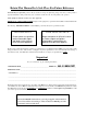
SECTION V WARRANTY INFORMATION A. RETURNING WARRANTY CARDS Before any dryer leaves the ADC factory test area, a warranty card is placed on the back side of the main door glass. These warranty cards are intended to serve the customer; we record the individual installation date and warranty information to better assist you should you file a warranty claim. If a warranty card did not come with your dryer, contact the ADC Warranty Department or the ADC Service Department at +1 (508) 678-9000.
2. Each part must be tagged with the following information: a. Model number and serial number of the dryer from which part was removed. b. Nature of failure. (Be specific). c. Date of dryer installation. d. Date of part failure. e. Specify whether the part(s) being returned is for a replacement, a credit, or a refund. NOTE: If a part is marked for a credit or a refund, the invoice number covering the purchase of the replacement part must be provided.
SECTION VI ROUTINE MAINTENANCE A. CLEANING A program and/or schedule should be established for periodic inspection, cleaning, and removal of lint from various areas of the dryer, as well as throughout the ductwork system. The frequency of cleaning can best be determined from experience at each location. Maximum operating efficiency is dependent upon proper air circulation. The accumulation of lint can restrict this airflow.
90 DAYS Remove lint from around basket (tumbler), drive motors, and surrounding areas. Remove lint from gas valve burner area with a dusting brush or vacuum cleaner attachment. Clean any lint that may have collected in and around the blower motor casing openings. IMPORTANT: To prevent damage, avoid cleaning or touching ignitor and flame-probe assembly. Remove lint accumulation from inside the control box and at the rear area behind the control box.
SECTION VII DATA LABEL INFORMATION When contacting American Dryer Corporation, certain information is required to ensure proper service/parts information from ADC. This information is on the data label located on the left side panel behind top/access control door. When contacting ADC, please have the model number and serial number available. 1. MODEL NUMBER – Describes the size of the dryer and the type of heat (gas, electric, or steam). 2.
SECTION VIII PROCEDURE FOR FUNCTIONAL CHECK OF REPLACEMENT COMPONENTS 1. Phase 7 Microprocessor Controller (Computer) Models a. Upon completing installation of the replacement microprocessor controller (computer) board, reestablish power to the dryer. b. Start the drying cycle by pressing any of the preset cycles in letters A-F. c. Verify that the applicable indicator lights on the microprocessor controller (computer) board are lit. (Refer to the illustration below.) 42 American Dryer Corp.
2. For Models with Direct Spark Ignition (DSI) Module (Type I) Theory of Operation: Start the drying cycle. When the gas burner ignites within the chosen trial for ignition time (6-seconds), the flame sensor detects gas burner flame and signals the DSI module to keep the gas valve open as long as there is a call for heat. The DSI module will “LOCKOUT” if the gas burner flame is not sensed at the end of the trial for ignition period.
SECTION IX MANUAL RESET BURNER HI-LIMIT INSTRUCTIONS A. PHASE 7 This dryer was manufactured with a manual reset burner hi-limit thermostat, which is monitored by the Phase 7 computer. If the burner hi-limit is open prior to the start of the drying cycle, the dryer will start momentarily and then shut down, the Phase 7 computer will display “burner HIGH LIMIT fault” with an audio indication.
Notes __________________________________________________________________________________________ ________________________________________________________________________________________________ ________________________________________________________________________________________________ ________________________________________________________________________________________________ ________________________________________________________________________________________________ ___________________________
ADC Part No.