
Clothes Dryer User Manual


12
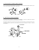
K. GAS BURNER
The gas burner assembly consists of two (2) burner
tube orifices (the orifice has a hole in it to allow
gas to flow through). The hole size varies with
different elevation Btus, gas valve (which can be
up for natural or liquid propane [L.P.]), and a
flame-probe assembly.
M. HI-LIMIT THERMOSTAT
The burner hi-limit thermostat is another safety device
that we use on the dryer. The hi-limit is located in
the burner area. The hi-limit thermostat cuts off the
heat if the temperature should reach 290° or higher.
Under normal conditions, the only way this device
would shut off the heat is when the airflow changes
to the extent of causing the intense heat from the
burner to trip the thermostat.
L. SAIL SWITCH
The sail switch consists of a round damper
plate on a lever arm, which acts like an
actuator for a microswitch. When the air
blower comes on, it draws air through the
burner. This creates a negative pressure inside
the burner box, and this negative pressure pulls
in the round damper, which activates the sail
switch. If there is improper airflow, the
damper will not pull in, preventing the burner
from coming on.
Improper airflow can be caused by improperly designed exhaust ducting, where the duct run is too long or has
too many sharp bends on it. It can also be caused by a lack of make-up air or any obstruction such as back draft
damper sticking or lint build up. The sail switch is located in the back of the burner.