
Clothes Dryer User Manual


45
(e) One (1) YELLOW or ORANGE wire supplies the 24 VAC signal for the control and/
or DSI circuit. (Refer to specific wiring diagram with the dryer for connection point.)
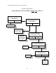
7) Direct Spark Ignition (DSI) 24 VAC Redundant Gas Valve
There are three (3) DSI 24 VAC Redundant Gas Valves in use (refer to the illustration below and
on the next page. The particular redundant gas valve that is used is dependent solely on the size
(model) of the dryer.
ALL three (3) redundant gas valves utilize 24 VAC, which is provided by the
DSI module. Their applications are as follows:
IMPORTANT: The DSI 24 VAC Redundant Gas Valves (ADC Part No. 128927) contain no
serviceable parts, replacement coils
ARE NOT available. Replace with exact model
and type number ONLY.
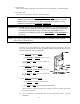
a) ADC PN 128927
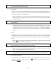
(1) To check the resistance values on this particular gas valve.
(a) Disconnect the terminations at the gas valve from the DSI module.
WARNING: When taking ohm readings, the terminations from DSI module must be disconnected,
removed, otherwise, the readings obtained will be incorrect and/or erroneous.
(2) With a meter (either a multimeter or ohmmeter) set on the 200 ohm position, place the
meter leads across:
(a) Terminals 1 and 2 - the reading should be approximately 96 ohms.
(b) Terminals 3 and 4 - the reading should be approximately 96 ohms.
(3) If, after checking the resistance values on this particular redundant gas valve it is determined
that the ohm readings DO NOT approximate the ohm values listed above (96 ohms for
both readings), then, the gas valve must be replaced.
ADC PN 128927 5N7 REDUNDANT GAS VALVE