
Clothes Dryer User Manual

48
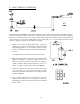
IMPORTANT: The Phase 5 coin microprocessor controller (computer) has its own internal heat
sensing circuit fuse protection, located on the back side of the controller. If a “dSFL”
condition occurs, check to see if this fuse has blown. If it has, DO NOT replace the
entire microprocessor controller (computer); replace the fuse and do so with a
1/8-amp (Slo-Blo) fuse only.
NOTE: Once the microprocessor controller (computer) detects a problem in the heat circuit, it updates
every 30-seconds. If the problem was a loose connection in this circuit, which corrected itself,
the “dSFL” condition would be cancelled.
3. “SEFL” - indicates rotational sensor circuit failure meaning that there is a fault somewhere in the basket
(tumbler) rotation detection circuit, or the Phase 5 coin microprocessor controller (computer)
program related to this circuit (PL 0.l) is set incorrectly in the active mode (SEn) where the dryer
is not equipped with the optional rotational sensor and should be set in the nonactive mode
(nSEn). Also check to see if the belt came loose, or the rotational sensor magnet is broken. If
not, adjust rotational sensor reed switch within 1/4” to the magnet.
4. “Hot” - indicates a possible overheating condition. The Phase 5 coin microprocessor controller (computer)
monitors the temperature in the dryer at ALL times. If the microprocessor controller (computer)
detects that the temperature in the dryer has exceeded 220° F (104° C), it will disable ALL outputs
(shut the dryer down), the tone (bUZ) will sound for approximately 5-seconds, and the light emitting
diode (L.E.D.) temperature sensor has dropped to 220° F (104° C) or lower and the microprocessor
controller (computer) is manually reset by closing and opening the program switch (PS) on the
back side of the controller.
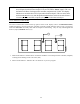
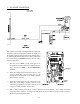
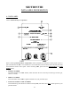
MICROPROCESSOR CONTROLLER (COMPUTER) RELAY OUTPUT L.E.D. INDICATORS
There are three (3) L.E.D. indicators (red lights) located at the lower backside area of the controller, they are
identified and labeled “dOOr,” “MOTOR,” and “HEAT” (as shown in the illustration on the next page). These
L.E.D.s indicate that the outputs of the Phase 5 coin microprocessor controller (computer) or, in the case of the
door switch, the input is functioning.
1. “dOOr” L.E.D. indicator should be on ALL the time (even if the dryer is not running) unless the main
door is open or there is a problem (open circuit) in the main door switch circuit.
2. “MOTOR” Output L.E.D. Indicator - if the dryer is started and the motor is not operating, yet both the
microprocessor controller (computer) display motor indicator dot and the “dOOr” input L.E.D.
indicator are on, but the motor output L.E.D. indicator is off, then the fault is in the Phase 5
coin microprocessor controller (computer) itself. If the motor is not operating and the MOTOR
output indicator is on, then the problem is elsewhere (i.e., external of the microprocessor
controller [computer]).
3. “HEAT” Output L.E.D. Indicator - If the dryer is started and there is no “heat,” yet the microprocessor
controller (computer) display heat circuit indicator dot is on, but the output L.E.D. indicator is
off, then the fault is in the Phase 5 coin microprocessor controller (computer) itself. If both the
display heat indicator dot and the heat output L.E.D. indicator are on, then the problem is
elsewhere (i.e., external of the microprocessor controller [computer]).