
Clothes Dryer User Manual

51
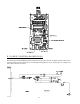
1. With the heat indicator on check for voltage at J1 connector 9-pin connector pin #8 (orange wire to ground)
if 24 volt is present.
2. If no voltage (24 VAC) check for loose connection at 9-pin
connector or problem may be faulty microprocessor.
3. Check for voltage (24 VAC) at J11 connector pin #3 orange
wire. If no voltage, check for loose connection or bad basket
(tumbler) hi-limit. If voltage is present, proceed to next step.
4. At the rear basket (tumbler) hi-limit take a voltage reading (24
VAC) from one of the red wires to ground. Do this on both
wires one at a time. If voltage
is not present, then the problem
is a loose connection going back to the sail switch or the sail
switch itself is faulty. If voltage is present on only one (1) of
the red wires, then the problem is a loose connection on the
rear basket (tumbler) hi-limit switch or the rear basket (tumbler)
hi-limit switch itself is faulty. If voltage (24 VAC) is present
from each red wire to ground then proceed to the next step.
5. Check for 24 VAC at the Direct Spark Ignition (DSI) module terminals marked “TH” and “GnD.” If no
voltage (24 VAC) is present check for a loose connection going back to the burner hi-limit or the burner
hi-limit itself may be faulty. If voltage (24 VAC) is present at the “TH” and “GnD” terminals proceed to
the next step.
6. If no spark is present, check for any hairline cracks at the base of the ignitor. If cracks are present replace
the ignitor. If no cracks are present, then the module (PN: 128935) may be faulty. If spark is occurring,
then proceed to Step #7.
7. Check for voltage (24 VAC) on the Direct Spark Ignition (DSI) module terminals marked “MV” and
“GnD” while the ignitor is sparking 24 VAC should be present on those two (2) terminals (“MV” and
“GnD”). If no voltage (24 VAC), then the problem is either a loose connection or a faulty DSI module (PN:
128935). If voltage is present proceed to next step.
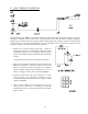
8. Check for 24 VAC at the gas valve terminals
marked 1 and 2. If no voltage (24 VAC) is
present check for a loose connection on the two
(2) wires at the gas valve or the DSI module (PN:
128935) may be faulty. If voltage (24 VAC) is
present proceed to next step.
9. Check the gas valve shutoff and make sure it is
in the “on” position. Check to ensure proper gas
pressure is being applied to the gas valve. If still
no ignition, use a manometer on the manifold side
of the gas valve. If the proper gas pressure is
not present while the ignitor is sparking the problem
is a faulty gas valve.