
Specifications


(4) The input voltage to any of the analog inputs must not exceed the reference voltage (nor should the input go
negative with respect to the reference) or erratic data may be generated on one or more of the analog channels.
When an external reference is used, the reference voltage must be within 100 millivolts of the supply voltage to the
ADC0809 IC (approximately 5 volts DC) when operating in a MODE (2) jumper configuration (see pages 10 & 11).
When operating in a MODE (3) jumper configuration (8 bit only), the reference voltage must be a minimum of 1.2
volts and the reference voltage must be centered about the supply voltage to the ADC0809 IC. When operating in a
MODE (3) jumper configuration, the input voltage to any of the analog inputs must not exceed the reference voltage
(nor should the input go negative with respect to the reference) or erratic data may be generated on one or more of
the analog channels.
Please contact EECI Support at (800) 842-7714 or (937) 349-6000 if you require additional assistance or have
questions.
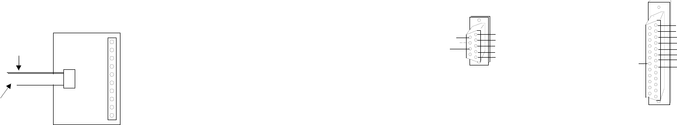
CONNECTOR PIN-OUTS
DB-9 CONNECTOR...SOCKET (female)
(rear view/solder side)
DB-25 CONNECTOR...SOCKET (female)
(rear view/solder side)
DB-9 Pins Connection
DB-25 Pins Connection
(1) Data Carrier Detect* (connect to black
wire or terminal (S) on the ADC-16) (2) Transmitted Data (connect to white wire
NOTE: This connection is not needed on or terminal (R) on the ADC-16)
most computers.
(3) Received Data (connect to green wire
(2) Received Data (connect to green wire or terminal (T) on the ADC-16)
or terminal (T) on the ADC-16)
(7) Signal Ground (connect to red wire or
(3) Transmitted Data (connect to white wire terminal (-) on the ADC-16)
or terminal (R) on the ADC-16)
(8) Data Carrier Detect* (connect to black
(5) Signal Ground (connect to red wire or wire or terminal (S) on the ADC-16)
terminal (-) on the ADC-16) NOTE: This connection is not needed on
most computers.
The following pins are optional and may be used
as needed for specific applications. The following pins are optional and may be
used as needed for specific applications.
(4) Data Terminal Ready (DTR) output from
your PC. (4) Request to Send (RTS) output from your PC.
(6) Data Set Ready (DSR) input to your PC. (5) Clear to Send (CTS) input to your PC.
(7) Request To Send (RTS) output from your PC. (6) Data Set Ready (DSR) input to your PC.
(8) Clear To Send (CTS) input to your PC. (20) Data Terminal Ready (DTR) output from your PC.
Page 5
(20) Data Terminal Ready
(1) Data Carrier Detect
(2) Received Data
(3) Transmitted Data
(4) Data Terminal Ready
(5) Signal Ground
(6) Data Set Ready
(7) Request to Send
(8) Clear to Send
(1) Equipment Ground
(2) Transmitted Data
(3) Received Data
(4) Request to Send
(5) Clear to Send
(6) Data Set Ready
(7) Signal Ground
(8) Data Carrier Detect
additional testing is desired, connect a 10k ohm 20 turn potentiometer to each input (one at a time) as shown on page
12, figure B. The input shown on the screen should increment from 0 to 255 (8 bit) or 0 to 1023 (10 bit). The number
shown for each input should increment by one (in 256 increments for 8 bit inputs) or (in 1024 increments for 10 bit
inputs) as the potentiometer is slowly adjusted from 0 to 20 turns.
(5) If operation of the analog inputs are normal, then testing is now complete and your ADC-16 may be placed in
service. If problems are encountered during testing, proceed to the trouble-shooting procedures shown below.
NOTE: The (S) terminal on the ADC-16 is provided for use as an RS-232 control signal for use with the RS-232 control
lines CTS, DSR and DCD. If the ADC-16 does not function with custom software, connect the (S) terminal (black wire)
to all three control lines (CTS, DSR and DCD). The pins for these control lines on a DB-9 connector are pins 8, 6 and 1.
The (S) terminal may also be used to supply a signal to one of the RS-232 control lines for use as a supervisory signal
to sound an alarm with your software when the ADC-16 has lost power or has been disconnected (see utilities).
RCT-8 CONNECTION DIAGRAM
TROUBLE-SHOOTING THE ADC-16
(1) Verify power to the ADC-16 by checking for 5 volts DC on the 2200 mf capacitor (low voltage may indicate an
overload). Verify that the ADC-16 is set to the same baud rate as what appears on the test software screen. Check for a
minimum of 9 volts DC at the ADC-16 power input (on the 6 position terminal block) and check for correct polarity. The
RS-232 driver on the ADC-16 requires a minimum of 9 volts for proper operation. A voltage over 14 volts will cause
damage to the RS-232 driver.
(2) Check the Com Port used with the ADC-16. Open device manager by clicking on the "Open Device Manager"
button on your installation CD (or by going to control panel). Click the small triangle (or +) to the left of Ports to
expand the Ports category, right click on the Com port that you have the ADC-16 connected to and click properties.
Check the Com port status and verify that you have the test program set to this Com port and verify that you have the
ADC-16 connected to this Com port.
If you are connecting the ADC-16 to a USB port, the Com port entry must be "Prolific USB to Serial Comm Port".
Right click on this entry, click properties and open the Driver tab. Your USB Com driver must be Prolific version
3.4.62.293 or higher (dated 10/17/2013 or later). If your USB Com driver is not up to date, then right click the "Prolific
USB to Serial Comm Port" entry and click update driver. If you do not see a "Prolific USB to Serial Comm Port" entry
then the USB cable driver is not correctly installed. You may re-install the driver from the supplied CD or Windows
Update. You may verify that you have the ADC-16 connected to this "Prolific USB to Serial Comm Port" entry by
watching the entry and unplugging the ADC-16 USB cable from your computer. The entry should disappear and then
re-appear when you re-connect the USB cable to the ADC-16.
(3) If erratic operation is experienced, check for loose connections at the ribbon cable connections and terminal block
(tug on each wire going into the terminal block), check for power supply interruptions or short circuits caused by metal
contact to the ADC-16 circuit areas or other connected hardware. When more than three EX-16 cards are connected
to the ADC-16, an external power feed is required (see EX-16 manual).
NOTE 3: With some programming languages the semicolon (;) at the end of the command is used to suppress the
carriage return and line feed. A line feed will transmit a "10" and a carriage return will transmit a "13".
Page 4
RCT-8
Analog Input #1
Analog Input #2
Analog Input #3
Analog Input #4
Analog Input #5
Analog Input #6
Analog Input #7
Analog Input #8
(+ Reference)
(- Reference)
Red Line
Ribbon Cable to
ADC-16
NOTE: The RCT-16 will
have the same connections
as two RCT-8