AD-758DV (Gas/Ph5/Dual Timer/DSI/1,000 cfm/Electric/Steam) Installation Manual WARNING: For your safety the information in this manual must be followed to minimize the risk of fire or explosion or to prevent property damage, personal injury or death. AVERTISSEMENT: Assurez-vous de bien suivre les instructions données dans cette notice pour réduire au minimum le risque d’incendie ou d’explosion ou pour éviter tout dommage matériel, toute blessure ou la mort.
Retain This Manual In A Safe Place For Future Reference American Dryer Corporation products embody advanced concepts in engineering, design, and safety. If this product is properly maintained, it will provide many years of safe, efficient, and trouble-free operation. ONLY qualified technicians should service this equipment. OBSERVE ALL SAFETY PRECAUTIONS displayed on the equipment or specified in the installation manual included with the dryer.
IMPORTANT YOU MUST DISCONNECT AND LOCKOUT THE ELECTRIC SUPPLYAND THE GAS SUPPLY OR THE STEAM SUPPLY BEFORE ANY COVERS OR GUARDS ARE REMOVED FROM THE MACHINE TO ALLOW ACCESS FOR CLEANING, ADJUSTING, INSTALLATION, OR TESTING OF ANY EQUIPMENT PER OSHA (Occupational Safety and Health Administration) STANDARDS. “Caution: Label all wires prior to disconnection when servicing controls. Wiring errors can cause improper operation.
WARNING The dryer must never be operated with any of the back guards, outer tops, or service panels removed. PERSONAL INJURY OR FIRE COULD RESULT. WARNING DRYER MUST NEVER BE OPERATED WITHOUT THE LINT FILTER/SCREEN IN PLACE, EVEN IF AN EXTERNAL LINT COLLECTION SYSTEM IS USED. IMPORTANT PLEASE OBSERVE ALL SAFETY PRECAUTIONS displayed on the equipment and/or specified in the installation manual included with the dryer.
Table of Contents SECTION I IMPORTANT INFORMATION ............................................................................... 3 A. Receiving and Handling ............................................................................................................... 3 B. Safety Precautions ...................................................................................................................... 4 SECTION II SPECIFICATIONS/COMPONENT IDENTIFICATION .................................... 6 A.
SECTION VI ROUTINE MAINTENANCE .................................................................................. 42 A. B. C. D. Cleaning .................................................................................................................................... 42 Adjustments .............................................................................................................................. 43 Lubrication ...................................................................................
SECTION I IMPORTANT INFORMATION A. RECEIVING AND HANDLING The dryer is shipped in a protective stretch wrap cover with protective cardboard corners and top cover (or optional box) as a means of preventing damage in transit. Upon delivery, the dryer and/or packaging, and wooden skid should be visually inspected for shipping damage. If any damage whatsoever is noticed, inspect further before delivering carrier leaves. Dryers damaged in shipment: 1.
B. SAFETY PRECAUTIONS WARNING: For your safety, the information in this manual must be followed to minimize the risk of fire or explosion or to prevent property damage, personal injury, or loss of life. WARNING: The dryer must never be operated with any of the back guards, outer tops, or service panels removed. PERSONAL INJURY OR FIRE COULD RESULT. 1. DO NOT store or use gasoline or other flammable vapors and liquids in the vicinity of this or any other appliance. 2.
7. A program should be established for the inspection and cleaning of lint in the burner area, exhaust ductwork, and area around the back of the dryer. The frequency of inspection and cleaning can best be determined from experience at each location. WARNING: The collection of lint in the burner area and exhaust ductwork can create a potential fire hazard. 8. For personal safety, the dryer must be electrically grounded in accordance with local codes and/or the National Electrical Code ANSI/NFPA NO.
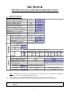
SECTION II SPECIFICATIONS/COMPONENT IDENTIFICATION A. SPECIFICATIONS GAS MAXIMUM CAPACITY (DRY WEIGHT) BASKET (TUMBLER) DIAMETER BASKET (TUMBLER) DEPTH BASKET (TUMBLER) MOTOR DOOR OPENING (DIAMETER) BASKET (TUMBLER) VOLUME EXHAUST CONNECTION (DIAMETER) AIRFLOW DRYERS PER 20'/40' CONTAINER DRYERS PER 48'/53' TRUCK VOLTAGE AVAILABLE APPROX. WEIGHT (UNCRATED) 75 lbs 37” 36” 1 HP* 21-1/2” 22.4 cu. ft. 8” 1,000 cfm 34 kg 94 cm 91.5 cm 0.745 kw 54.61 cm 0.634 cu.m. 20.3 cm 28.
Specifications AD-758DV (Gas/Electric/Steam) NOTE: ADC reserves the right to make changes in specifications at any time without notice or obligation.
B. COMPONENT IDENTIFICATION 1. Dryer Front View Illus. No.
2. Dryer Rear View Illus. No.
SECTION III INSTALLATION PROCEDURES Installation should be performed by competent technicians in accordance with local and state codes. In the absence of these codes, the installation must conform to applicable American National Standards: ANSI Z223.1LATEST EDITION (National Fuel Gas Code) or ANSI/NFPA NO. 70-LATEST EDITION (National Electrical Code) or in Canada, the installation must conform to applicable Canadian Standards: CAN/CGA-B149.1-M91 (Natural Gas) or CAN/CGA-B149.2-M91 (Liquid Propane [L.P.
CAUTION: This dryer produces combustible lint and must be exhausted to the outdoors. Every six (6) months, inspect the exhaust ducting and remove any lint build up. B. UNPACKING/SETTING UP Remove protective shipping material (i.e., plastic wrap and/or optional shipping box) from dryer. IMPORTANT: Dryer must be transported and handled in an upright position at ALL times. The dryer can be moved to its final location while still attached to the skid or with the skid removed.
C. DRYER ENCLOSURE REQUIREMENTS Bulkheads and partitions should be made of noncombustible materials and must be located a minimum of 12-inches (30.48 cm), 18-inches (45.72 cm) or more is recommended for ease of installation, maintenance, and service above the dryer’s outer top, except along the front of the dryer which may be partially closed in if desired. The clearance between the bulkhead header and the dryer must be a minimum of 4-inches (10.16 cm) and must not extend more than 4-inches (10.
D. FRESH AIR SUPPLY REQUIREMENTS When the dryer is operating, it draws in room air, heats it, passes this air through the basket (tumbler), and exhausts it out of the building. Therefore, the room air must be continually replenished from the outdoors. If the make-up air is inadequate, drying time and drying efficiency will be adversely affected. Ignition problems and sail switch “fluttering” problems may result, as well as premature motor failure from overheating.
E. EXHAUST REQUIREMENTS 1. General Exhaust Ductwork Information Exhaust ductwork should be designed and installed by a qualified professional. Improperly sized ductwork will create excessive back pressure which results in slow drying, increased use of energy, overheating of the dryer, and shutdown of the burner by the airflow (sail) switches, burner hi-limits, or basket (tumbler) hi-heat thermostats. The dryer must be installed with a proper exhaust duct connection to the outside.
IMPORTANT: Exhaust back pressure measured by a manometer in the exhaust duct must be no less than 0 and must not exceed 0.7 inches (1.74 mb) of water column (W.C.). NOTE: When the exhaust ductwork passes through a wall, ceiling, or roof made of combustible materials, the opening must be 2-inches (5.08 cm) larger than the duct (all the way around). The duct must be centered within this opening. a.
IMPORTANT: For extended ductwork runs, the cross section area of the ductwork can only be increased to an extent. When the ductwork approaches the maximum limits noted in this manual, a professional heating, venting, and air conditioning (HVAC) firm should be consulted for proper venting information. ALL ductwork should be smooth inside with no projections from sheet metal screws or other obstructions, which will collect lint.
3. Multiple (Common) Dryer Venting IMPORTANT: For extended ductwork runs, the cross section area of the ductwork can only be increased to an extent. When the ductwork approaches the maximum limits noted in this manual, a professional heating, venting, and air conditioning (HVAC) firm should be consulted for proper venting information. ALL ductwork should be smooth inside with no projections from sheet metal screws or other obstructions, which will collect lint.
IMPORTANT VENTING REMINDERS 1. Ductwork size and installation should be done by a qualified professional. 2. The dryer must be exhausted to the outdoors. 3. Ductwork should be routed as short as possible to the outdoors with as few elbows as possible. 4. Avoid 90° turns, use 30° or 45° turns instead. 5. For single dryer venting, the size of the ductwork must be a minimum of 8-inches (20.32 cm) for short runs (refer to the illustration on page 16). For longer runs, the diameter must be increased. 6.
F. ELECTRICAL INFORMATION 1. Electrical Requirements It is your responsibility to have ALL electrical connections made by a properly licensed and competent electrician to assure that the electrical installation is adequate and conforms to local and state regulations or codes. In the absence of such codes, ALL electrical connections, materials, and workmanship must conform to the applicable requirements of the National Electrical Code ANSI/NFPA NO.
2) Electric Models ONLY ALL electrically heated dryers must be connected to the electric service shown on the dryer’s data label, which is affixed to the upper left side panel area behind the top control (access) door. The connecting wires must be properly sized to handle the rated current. NOTE: Electrically heated service (amperage) specifications/requirements are not available at the time of printing. Contact factory for update.
SINGLE-PHASE (1Ø) ELECTRICAL CONNECTIONS LEADS Black + Positive White Neutral Green Ground or L2 If local codes permit, power to the dryer can be made by the use of a flexible U.L. listed power cord or pigtail (wire size must conform to rating of dryer), or the dryer can be hard wired directly to the service breaker panel. In both cases, a strain relief must be installed where the wiring enters the dryer.
5. 3-Phase (3ø) Wiring Connections/Hookup (For Non-Reversing Models Only) The only electrical input connections to the dryer are the 3-phase (3ø) power leads (L1, L2, L3, and sometimes Neutral) and ground. Single-phase (1ø) power for the control circuit is done internally to the dryer. No single-phase (1ø) input connection is required on a 3-phase (3ø) dryer. IMPORTANT: A CIRCUIT SERVICING EACH DRYER MUST BE PROVIDED. a.
6. 3-Phase (3ø) Wiring Connections/Hookup (for Reversing Models Only) The electrical connections on ALL 3-phase (3ø) gas dryers and steam dryers are made into the rear service box located at the upper left area of the dryer. Electrical connections for electrically heated dryers are made in the electric oven area located at the upper rear area of the dryer. IMPORTANT: A separate circuit servicing each dryer must be provided.
CAUTION: The dryer must be grounded. A ground lug has been provided for this purpose. IMPORTANT: A CIRCUIT SERVICING EACH DRYER MUST BE PROVIDED. The only electrical connections to the dryer are the 3-phase (3ø) leads (L1, L2, L3, and sometimes neutral) and ground. NOTE: Electrically heated service (amperage) specifications/requirements are not available at the time of printing. Contact factory for update.
ADG-758DV (GAS) ADS-758DV (STEAM ) ELECTRICAL SERVICE SPECIFICATIONS (PER DRYER) IMPORTANT: 208 VAC AND 240 VAC ARE NOT THE SAME. When ordering, specify exact voltage. NOTES: A. When fuses are used they must be dual element, time delay, current limiting, class RK1 or RK5 ONLY. Calculate/determine correct fuse value, by applying either local and/or National Electrical Codes listed appliance amp draw data. B. Circuit breakers are thermal-magnetic (industrial) motor curve type ONLY.
G. GAS INFORMATION It is your responsibility to have ALL plumbing connections made by a qualified professional to assure that the gas plumbing installation is adequate and conforms to local and state regulations or codes. In the absence of such codes, ALL plumbing connections, materials, and workmanship must conform to the applicable requirements of the National Fuel Gas Code ANSI Z223.1-LATEST EDITION, or in Canada, the Canadian Installation Codes CAN/CGA-B149.1-M91 (Natural Gas) or CAN/CGA-B149.
2. Technical Gas Data a. Gas Specifications TYPE OF GAS NATURAL Manifold Pressure* In-Line Pressure LIQUID PROPANE 3.5 inches W.C. 8.7 mb 10.5 inches W.C. 26.1 mb 6.0 - 12.0 inches W.C. 14.92 - 29.9 mb 11.0 inches W.C. 27.4 mb Shaded areas are stated in metric equivalents * Measured at outlet side of gas valve pressure tap when gas valve is on. b. Gas Connections Inlet connection ------------------- 3/4” N.P.T. Inlet supply size ------------------- 3/4” N.P.T.
3. Piping/Connections ALL components/materials must conform to National Fuel Gas Code Specifications ANSI Z223.1-LATEST EDITION, or in Canada, CAN/CGA-B149.1-M91 (Natural Gas) or CAN/CGA-B149.2-M91 (Liquid Propane [L.P.] Gas) or LATEST EDITION (for General Installation and Gas Plumbing), as well as local codes and ordinances and must be done by a qualified professional.
Consistent gas pressure is essential at ALL gas connections. It is recommended that a 3/4-inch (19.05 mm) pipe gas loop be installed in the supply line servicing a bank of dryers. An in-line pressure regulator must be installed in the gas supply line (header) if the (natural) gas pressure exceeds 12.0 inches (29.9 mb) of water column (W.C.) pressure. NOTE: A water column test pressure of 3.5 inches (8.7 mb) for natural gas and 10.5 inches (26.1 mb) for liquid propane (L.P.
H. STEAM INFORMATION It is your responsibility to have ALL plumbing connections made by a qualified professional to assure that the steam plumbing installation is adequate and conforms with local and state regulations or codes. Care must be exercised when leveling steam dryers into final position. After leveling the dryer, check the downward pitch of the heat exchanger from front to rear with a level. Likewise, check the downward pitch of the return condensate manifold toward its outlet part.
IMPORTANT: Steam coil failure due to water hammer by wet steam will VOID THE WARRANTY. a. The pressure of the condensate in the steam supply will cause water hammer and subsequent heat exchanger (steam coil) failure. The steam supply connection into the main supply line must be made with a minimum 10-inch (25.4 cm) riser. This will prevent any condensate from draining towards the dryer. b. The steam supply piping to the dryer must include a 12-inch (30.48 cm) rise along with a drip trap and check valve.
4. Steam Damper Air System Connections The ADS-758DV is manufactured with a pneumatic (piston) damper system, which requires an external supply of compressed air. The air connection is made to the steam damper solenoid valve, which is located at the rear inner top area of the dryer just in front of the electric service relay box. a. Air Requirements There is no air requirement for dryers with the Electromechanical Steam Damper Option. COM PRESSED AIR SUPPLY AIR PRESSURE NORMAL 80 PSI 5.
c. Air Regulation No air regulator or filtration is provided with the dryer. External regulation/filtration of 80 PSI (5.51 bars) must be provided. It is suggested that a regulator/filter gauge arrangement be added to the compressed air line just before the dryer connection. This is necessary to insure that correct and clean air pressure is achieved. 5.
6. Steam Damper Air Piston (Flow Control) Operation Adjustment Damper operation was tested and adjusted prior to shipping at 80 PSI (5.51 bars). If damper air adjustment is necessary, locate the flow control valve and make the necessary adjustments as noted below.
I. PREPARATION FOR OPERATION/START-UP The following items should be checked before attempting to operate the dryer: 1. Read ALL “CAUTION,” “WARNING,” and “DIRECTION” labels attached to the dryer. 2. Check incoming supply voltage to be sure that it is the same as indicated on the dryer data label affixed to the upper left side panel area behind the top control (access) door. In the case of 208 VAC or 240 VAC, the supply voltage must match the electric service specifications of the data exactly. 3.
J. PREOPERATIONAL TESTS ALL dryers are thoroughly tested and inspected before leaving the factory. However, a preoperational test should be performed before the dryer is publicly used. It is possible that adjustments have changed in transit or due to marginal location (installation) conditions. 1. Turn on electric power to the dryer. 2. Refer to the Operating Instructions for starting your particular model dryer. 3. GAS MODELS ONLY a.
NOTE: To check for proper sail switch operation (for gas and electric models only), open the main door and while holding main door switch plunger in, start dryer. Dryer should start but heat circuit should not be activated (on). If the heat system is activated, the sail switch is improperly adjusted and must be adjusted by bending the actuator arm of the sail switch toward the burner box. If the actuator arm is bent too far toward the burner box of the dryer, the dryer may not have heat when needed.
K. PREOPERATIONAL INSTRUCTIONS OPL MODELS 1. To start the dryer: a. Microprocessor controller (computer) dryers 1) The light emitting diode (L.E.D.) display will read “FILL.” 2) Press the “E” on the keyboard (touch pad). 3) The L.E.D. display will quickly show “Ld30,” “LC04,” “F180.” The dryer will start, and the L.E.D. display will show “dr30.” b. Dual timer dryers... 1) Turn drying timer knob for a time of 20 minutes. 2) Select “High Temp.” 3) Push “Push To Start” switch.
SECTION IV SERVICE/PARTS INFORMATION A. SERVICE 1. Service must be performed by a qualified trained technician, service agency, or gas supplier. If service is required, contact the reseller from whom the ADC equipment was purchased. If the reseller cannot be contacted or is unknown, contact the ADC Service Department for a reseller in your area.
SECTION V WARRANTY INFORMATION A. RETURNING WARRANTY CARDS 1. Before any dryer leaves the ADC factory test area, a warranty card is placed on the back side of the main door glass. These warranty cards are intended to serve the customer where we record the individual installation date and warranty information to better serve you should you file a warranty claim. a. If a warranty card did not come with your dryer, contact the ADC Warranty Department or the ADC Service Department at (508) 678-9000.
2. Each part must be tagged with the following information: a. Model number and serial number of the dryer from which part was removed. b. Nature of failure (be specific). c. Date of dryer installation. d. Date of part failure. e. Specify whether the part(s) being returned is for a replacement, a credit, or a refund. NOTE: If a part is marked for a credit or a refund, the invoice number covering the purchase of the replacement part must be provided. NOTE: Warranty tags (ADC Part No.
SECTION VI ROUTINE MAINTENANCE A. CLEANING A program and/or schedule should be established for periodic inspection, cleaning, and removal of lint from various areas of the dryer, as well as throughout the ductwork system. The frequency of cleaning can best be determined from experience at each location. Maximum operating efficiency is dependent upon proper air circulation. The accumulation of lint can restrict this airflow.
WARNING: When cleaning steam coil fins, be careful not to bend the fins. If fins are bent, straighten by using a fin comb, which is available from local air conditioning supply houses. 90 DAYS Inspect and remove lint accumulation in customer furnished exhaust ductwork system and from dryer’s internal exhaust ducting. WARNING: THE ACCUMULATION OF LINT IN THE EXHAUST DUCTWORK CAN CREATE A POTENTIAL FIRE HAZARD. WARNING: DO NOT OBSTRUCT THE FLOW OF COMBUSTION AND VENTILATION AIR.
D. LINT DRAWER REMOVAL To remove the lint drawer from the dryer pull drawer out approximately halfway. Rotate/move lint drawer stop hinge (refer to the illustration below) downward and pull drawer out. IMPORTANT: After replacing the lint drawer back into the dryer, be sure to rotate/move hinge back to the upward stop position.
SECTION VII TROUBLESHOOTING IMPORTANT: YOU MUST DISCONTINUE AND LOCKOUT THE ELECTRIC SUPPLY AND THE GAS SUPPLY OR THE STEAM SUPPLY BEFORE ANY COVERS OR GUARDS ARE REMOVED FROM THE DRYER TO ALLOW ACCESS FOR CLEANING, ADJUSTING, INSTALLATION, OR TESTING OF ANY EQUIPMENT PER OSHA (Occupational Safety and Health Administration) STANDARDS. The information provided will help isolate the most probable component(s) associated with the difficulty described.
3. Failed drive motor. 4. Failed microprocessor controller (computer). C. Drive motor (reversing) operates in one (1) direction ONLY, stops and restarts in same direction... 1. Failed drive motor contactor (relay). 2. Failed arc suppressor (A.S.) board (for Reversing Models Only). 3. Failed microprocessor controller (computer). D. Drive motor operates okay for a few minutes and then stops and will not restart... 1. Motor is overheating and tripping out on internal overload protector... a.
1. Fault in main door switch circuit. 2. Blown fuse (2-amp very fast acting fuse [if applicable]). 3. Failed arc suppressor (A.S.) board (for Reversing Models Only). 4. Failed microprocessor controller (computer). 5. Failed 24 VAC transformer. H. Both drive motor and blower motor run a few minutes and then stop...microprocessor controller (computer) display continues to read time or percent of extraction and ALL indicator dots are off... 1. Fault in main door switch circuit... a. Failed main door switch.
L. Microprocessor controller (computer) will ONLY accept certain keyboard (touch pad) entries... 1. Failed keyboard (touch pad) label assembly. 2. Failed microprocessor controller (computer). M. Microprocessor controller (computer) locks up and light emitting diode (L.E.D.) display reads erroneous message(s) or ONLY partial segments... 1. Transient power voltage (spikes)...disconnect power to dryer, wait 1 minute, and reestablish power to dryer. If problem is still evident... a.
b. Sail switch damper is not closing or is fluttering... 1) Lint screen is dirty. 2) Restriction in exhaust ductwork. 2. Fault in burner hi-limit circuit or tripped manual reset hi-limit. 3. Fault in lint chamber sensor bracket or tripped manual reset hi-heat protector thermostat. 4. Failed Direct Spark Ignition (DSI) module. 5. Failed DSI ignitor/flame-probe assembly. 6. Failed microprocessor controller (computer). ELECTRIC MODELS ONLY 1. Fault in sail switch circuit... a.
Q. Dryer operates but is taking too long to dry... 1. Exhaust ductwork run too long or is undersized...back pressure must be no less than 0 and must not exceed 0.3 inches (0.75 mb) of water column (W.C.). 2. Restriction in exhaust ductwork... a. Exhaust back draft damper is sticking partially closed. b. Restriction in ductwork...check ductwork from dryer ALL the way to the outdoors. 3. Low and/or inconsistent gas pressure (for Gas Models Only). 4. Insufficient make-up air. 5. Poor air/gas mixture at burner.
3. Loose basket (tumbler) tie rod. 4. Failed basket (tumbler) support. T. Excessive noise and/or vibration... 1. Dryer is not leveled properly. 2. Impellor (fan/blower) is out of balance... a. Excessive lint build up on impellor (fan/blower). b. Failed impellor (fan/blower). 3. Loose basket (tumbler) tie rod. 4. Basket (tumbler) is out of adjustment or adjustment bolts (hardware) are loose. 5. Failed basket (tumbler) support. 6. Loose motor mount. 7. Failed idler and/or basket (tumbler) bearings. 8.
6. Failed dual timer relay. B. Drive motor (ONLY) is not operating... 1. Failed drive motor contactor. 2. Failed reversing timer (for Reversing Models Only). 3. Failed drive motor. C. Blower motor (ONLY) is not operating... 1. Failed impellor (fan/blower) motor contactor (relay). 2. Failed blower (impellor/fan) motor. D. Both drive motor and blower motor are not operating (indicator light is on)... 1. Fault with L1 termination at reversing timer (for Reversing Models Only). 2. Failed drying timer. E.
ELECTRIC MODELS ONLY 1. Fault in sail switch circuit... a. Sail switch is out of adjustment or has failed. b. Sail switch is not closing or fluttering... 1) Check blower (impellor/fan) motor and rotation direction. 2) Restriction in location exhaust system. 2. Failed oven hi-limit circuit. 3. Tripped lint compartment manual reset (225º F [107º C]) safety thermostat circuit. 4. Failed oven contactor/relay. 5. Failed heat selector switch. STEAM MODELS ONLY 1. Steam damper binding and/or stuck. 2.
6. Failed hi-limit thermostat (for Electric Models Only). 7. Extractors (washers) are not performing properly. 8. Low and/or inconsistent gas pressure (for Gas Models Only). 9. Gas supply may have low heating value (for Gas Models Only). 10. Sail switch is fluttering (for Gas and Electric Models Only)... a. Restriction in location exhaust system. 11. Fault in electric oven element circuit (for Electric Models Only)... a. Failed element(s). b. Failed oven contactor (relay). 12.
SECTION VIII DATA LABEL INFORMATION A. DATA LABEL Contact American Dryer Corporation When contacting American Dryer Corporation certain information is required to insure proper service/parts information from ADC. This information is on the data label affixed to the upper left side panel area behind the top control (access) door. When contacting ADC please have the model number and serial number available.
THE DATA LABEL 1. MODEL NUMBER The model number is an ADC number, which describes the size of the dryer and the type of heat (gas, electric, or steam). 2. SERIAL NUMBER The serial number allows ADC to gather information on your particular dryer. 3. MANUFACTURING CODE NUMBER The manufacturing code number is a number issued by ADC, which describes ALL possible options on your particular model. 4.
SECTION IX REVERSING TIMER SPIN/DWELL ADJUSTMENTS Dual timer models with “reversing option” have an electric reversing timer in the electric service box, which is located in the upper rear area of the dryer. Both the dwell (stop) time and basket (tumbler) spin time are adjustable by mode selection switches located on the electronic timer (as noted in the illustration below).
SECTION X PROCEDURE FOR FUNCTIONAL CHECK OF REPLACEMENT COMPONENTS 1. Microprocessor Controller (Computer) Board a. Upon completing installation of the replacement microprocessor controller (computer) board, reestablish power to the dryer. b. Start the drying cycle. c. Verify that the motor(s) and the heat indicator dots, in the microprocessor controller (computer) light emitting diode (L.E.D.) display are on. (Refer to the illustration below.) d.
e. Open main door. The dryer must stop and ALL indicator lights on the back side of the microprocessor controller (computer) board must go out. (Refer to the illustration on the previous page.) f. Try to restart the dryer with the main door open. g. The microprocessor controller (computer) board’s light emitting diode (L.E.D.) display must read “DOOR.” h. Close the main door and restart the dryer. i. Functional check of microprocessor controller (computer) board is complete. 2.
ADC 113390 1 - 11/04/02-25