AD-758DV Installation Manual Phase 7 WARNING: For your safety the information in this manual must be followed to minimize the risk of fire or explosion or to prevent property damage, personal injury or death. AVERTISSEMENT: Assurez-vous de bien suivre les instructions données dans cette notice pour réduire au minimum le risque d’incendie ou d’explosion ou pour éviter tout dommage matériel, toute blessure ou la mort.
Retain This Manual In A Safe Place For Future Reference American Dryer Corporation products embody advanced concepts in engineering, design, and safety. If this product is properly maintained, it will provide many years of efficient, trouble free, and most importantly safe operation. ONLY qualified technicians should service this equipment. OBSERVE ALL SAFETY PRECAUTIONS displayed on the equipment or specified in the installation manual included with the dryer.
IMPORTANT YOU MUST DISCONNECT AND LOCKOUT THE ELECTRIC SUPPLYAND THE GAS SUPPLY OR THE STEAM SUPPLY BEFORE ANY COVERS OR GUARDS ARE REMOVED FROM THE MACHINE TO ALLOW ACCESS FOR CLEANING, ADJUSTING, INSTALLATION, OR TESTING OF ANY EQUIPMENT PER OSHA (Occupational Safety and Health Administration) STANDARDS. “Caution: Label all wires prior to disconnection when servicing controls. Wiring errors can cause improper operation.
WARNING The dryer must never be operated with any of the back guards, outer tops, or service panels removed. PERSONAL INJURY OR FIRE COULD RESULT. WARNING DRYER MUST NEVER BE OPERATED WITHOUT THE LINT FILTER/SCREEN IN PLACE, EVEN IF AN EXTERNAL LINT COLLECTION SYSTEM IS USED. IMPORTANT PLEASE OBSERVE ALL SAFETY PRECAUTIONS displayed on the equipment and/or specified in the installation manual included with the dryer.
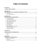
Table of Contents SECTION I SAFETY PRECAUTIONS ......................................................................................... 3 SECTION II SPECIFICATIONS/COMPONENT IDENTIFICATION ..................................... 5 A. Specifications ............................................................................................................................. 5 B. Component Identification ............................................................................................................
SECTION VI ROUTINE MAINTENANCE .................................................................................. 41 A. B. C. D. Cleaning ................................................................................................................................... 41 Adjustments ............................................................................................................................. 42 Lubrication .....................................................................................
SECTION I SAFETY PRECAUTIONS WARNING: For your safety, the information in this manual must be followed to minimize the risk of fire or explosion or to prevent property damage, personal injury, or loss of life. WARNING: The dryer must never be operated with any of the back guards, outer tops, or service panels removed. PERSONAL INJURY OR FIRE COULD RESULT. 1. DO NOT store or use gasoline or other flammable vapors and liquids in the vicinity of this or any other appliance. 2.
WARNING: DO NOT use heat for drying articles that contain plastic, foam, sponge rubber, or similarly textured rubber materials. Drying in a heated basket (tumbler) may damage plastics or rubber and may be a fire hazard. 7. A program should be established for the inspection and cleaning of lint in the burner area, exhaust ductwork, and area around the back of the dryer. The frequency of inspection and cleaning can best be determined from experience at each location.
SECTION II SPECIFICATIONS/COMPONENT IDENTIFICATION A.
Specifications – Gas, Electric, Steam NOTE: ADC reserves the right to make changes in specifications at any time without notice or obligation. 6 American Dryer Corp.
B. COMPONENT IDENTIFICATION 1. Dryer Front View Illus. No. 1 2 3 4 5 113230-5 Description Controls Control (top access) Door Assembly Main Door Assembly Lint Compartment Area (lint screen located behind lint door or left sidewall) Data Label and Installation Label www.amdry.
2. Dryer Rear View Illus. No. 1 2 3 4 5 6 7 8 8 Description Heating Unit Electric Service Relay Box Basket (tumbler) Bearing Mount Assembly Idler Bearing Mount Assembly Blower Motor Assembly (for reversing models only) Leveling Legs (rear) Basket (tumbler) (drive) Motor Assembly Dryer Exhaust American Dryer Corp.
SECTION III INSTALLATION PROCEDURES Installation should be performed by competent technicians in accordance with local and state codes. In the absence of these codes, the installation must conform to applicable American National Standards: ANSI Z223.1LATEST EDITION (National Fuel Gas Code) or ANSI/NFPA NO. 70-LATEST EDITION (National Electrical Code) or in Canada, the installation must conform to applicable Canadian Standards: CAN/CGA-B149.1-M91 (Natural Gas) or CAN/CGA-B149.2-M91 (Liquid Propane [L.P.
CAUTION: This dryer produces combustible lint and must be exhausted to the outdoors. Every 6 months, inspect the exhaust ducting and remove any lint buildup. IMPORTANT: Dryer must be installed in a location/environment, which the ambient temperature remains between 40º F (4.44º C) and 130º F (54.44º C). B. UNPACKING/SETTING UP Remove protective shipping material (i.e., plastic wrap and/or optional shipping box) from dryer.
C. DRYER ENCLOSURE REQUIREMENTS Bulkheads and partitions should be made of noncombustible materials and must be located a minimum of 12-inches (30.48 cm) (18-inches [45.72 cm] or more is recommended for ease of installation, maintenance, and service) above the dryer’s outer top, except along the front of the dryer, which may be partially closed in if desired. The clearance between the bulkhead header and the dryer must be a minimum of 4-inches (10.16 cm) and must not extend more than 4-inches (10.
D. FRESH AIR SUPPLY REQUIREMENTS When the dryer is operating, it draws in room air, heats it, passes this air through the basket (tumbler), and exhausts it out of the building. Therefore, the room air must be continually replenished from the outdoors. If the make-up air is inadequate, drying time and drying efficiency will be adversely affected. Ignition problems and sail switch “fluttering” problems may result, as well as premature motor failure from overheating.
E. EXHAUST REQUIREMENTS 1. General Exhaust Ductwork Information Exhaust ductwork should be designed and installed by a qualified professional. Improperly sized ductwork will create excessive back pressure, which results in slow drying, increased use of energy, overheating of the dryer, and shutdown of the burner by the airflow (sail) switches, burner hi-limits, or basket (tumbler) hi-heat thermostats. The dryer must be installed with a proper exhaust duct connection to the outside.
IMPORTANT: Exhaust back pressure measured by a manometer in the exhaust duct must be no less than 0 and must not exceed 0.7 inches (1.74 mb) of water column (W.C.). NOTE: When the exhaust ductwork passes through a wall, ceiling, or roof made of combustible materials, the opening must be 2-inches (5.08 cm) larger than the duct (all the way around). The duct must be centered within this opening.
IMPORTANT: For extended ductwork runs, the cross section area of the ductwork can only be increased to an extent. When the ductwork approaches the maximum limits noted in this manual, a professional heating, ventilating, and air-conditioning (HVAC) firm should be consulted for proper venting information. ALL ductwork should be smooth inside with no projections from sheet metal screws or other obstructions, which will collect lint.
3. Multiple (Common) Dryer Venting IMPORTANT: For extended ductwork runs, the cross section area of the ductwork can only be increased to an extent. When the ductwork approaches the maximum limits noted in this manual, a professional heating, ventilating, and air-conditioning (HVAC) firm should be consulted for proper venting information. ALL ductwork should be smooth inside with no projections from sheet metal screws or other obstructions, which will collect lint.
F. ELECTRICAL INFORMATION 1. Electrical Requirements ALL electrical connections must be made by a properly licensed and competent electrician. This is to ensure that the electrical installation is adequate and conforms to local and state regulations or codes. In the absence of such codes, ALL electrical connections, materials, and workmanship must conform to the applicable requirements of the National Electrical Code ANSI/NFPA NO.
2. Electrical Service Specifications a. Gas and Steam Models Only GAS AND STEAM ELECTRICAL SERVICE SPECIFICATIONS (PER DRYER) IMPORTANT: 208 VAC AND 230/240 VAC ARE NOT THE SAME. When ordering, specify exact voltage. NOTES: When fuses are used they must be dual element, time delay, current limiting, class RK1 or RK5 ONLY. Calculate/determine correct fuse value, by applying either local and/or National Electrical Codes to listed appliance amp draw data.
b. Electric Models Only ALL electrically heated dryers must be connected to the electric service shown on the dryer’s data label. The connecting wires must be properly sized to handle the rated current. ELECTRIC — 30 kW ELECTRICAL SERVICE SPECIFICATIONS (PER DRYER) IMPORTANT: 208 VAC AND 230/240 VAC ARE NOT THE SAME. When ordering, specify exact voltage. NOTES: When fuses are used they must be dual element, time delay, current limiting, class RK1 or RK5 ONLY.
For added personal safety, when possible, it is suggested that a separate ground wire (no. 18 minimum) be connected from the ground connection of the dryer to a grounded cold water pipe. DO NOT ground to a gas pipe or hot water pipe. The grounded cold water pipe must have metal-to-metal connection ALL the way to the electrical ground. If there are any nonmetallic interruptions, such as, a meter, pump, plastic, rubber, or other insulating connectors, they must be jumped out with no.
Single-Phase Electrical Lead Connections Black + Positive FOR 110V APPLICATIONS White or Red + Neutral or L2 Green + Ground FOR 208-230/240V APPLICATIONS A ground lug is provided in the rear electrical box to connect your service ground. 113230-5 www.amdry.
2) 3-Phase (3ø) Wiring Connections/Hookup The electrical connections on ALL 3-phase (3ø) gas and steam dryers are made into the rear service box located at the upper left area of the dryer. The electrical connections are made at the power distribution block located in the service box. The ground connection is made to the copper lug, also provided in this box. To gain access, the service box cover must be removed. The neutral will only be used on 4-wire service. This is typical for 380-416V, 50 Hz. b.
G. GAS INFORMATION It is your responsibility to have ALL plumbing connections made by a qualified professional to ensure that the gas plumbing installation is adequate and conforms to local and state regulations or codes. In the absence of such codes, ALL plumbing connections, materials, and workmanship must conform to the applicable requirements of the National Fuel Gas Code ANSI Z223.1-LATEST EDITION, or in Canada, the Canadian Installation Codes CAN/CGA-B149.1-M91 (Natural Gas) or CAN/CGA-B149.
2. Technical Gas Data a. Gas Specifications TYPE OF GAS NATURAL 3.5 inches W.C. 8.7 mb 10.5 inches W.C. 26.1 mb 6.0 - 12.0 inches W.C. 14.92 - 29.9 mb 11.0 inches W.C. 27.4 mb Manifold Pressure* In-Line Pressure LIQUID PROPANE Shaded areas are stated in metric equivalents * Measured at outlet side of gas valve pressure tap when gas valve is on. b. Gas Connections Inlet connection ------------------- 3/4” N.P.T. Inlet supply size ------------------- 3/4” N.P.T.
3. Piping/Connections ALL components/materials must conform to National Fuel Gas Code Specifications ANSI Z223.1-LATEST EDITION, or in Canada, CAN/CGA-B149.1-M91 (Natural Gas) or CAN/CGA-B149.2-M91 (Liquid Propane [L.P.] Gas) or LATEST EDITION (for General Installation and Gas Plumbing), as well as local codes and ordinances and must be done by a qualified professional.
Consistent gas pressure is essential at ALL gas connections. It is recommended that a 3/4-inch (19.05 mm) pipe gas loop be installed in the supply line servicing a bank of dryers. An in-line pressure regulator must be installed in the gas supply line (header) if the (natural) gas pressure exceeds 12.0 inches (29.9 mb) of water column (W.C.) pressure. NOTE: A water column test pressure of 3.5 inches (8.7 mb) for natural gas and 10.5 inches (26.1 mb) for liquid propane (L.P.
H. STEAM INFORMATION It is your responsibility to have ALL plumbing connections made by a qualified professional to ensure that the steam plumbing installation is adequate and conforms with local and state regulations or codes. Care must be exercised when leveling steam dryers into final position. After leveling the dryer, check the downward pitch of the heat exchanger from front to rear with a level. Likewise, check the downward pitch of the return condensate manifold toward its outlet part.
a. The pressure of the condensate in the steam supply line will cause water hammer and subsequent heat exchanger (steam coil) failure. The steam supply connection into the main supply line must be made with a minimum 10-inch (25.4 cm) riser. This will prevent any condensate from draining towards the dryer. b. The steam supply line to the dryer must include a 12-inch (30.48 cm) riser along with a drip trap and check valve. This will prevent any condensate from entering the steam coil. c.
4. Steam Damper Air System Connections This dryer is manufactured with a pneumatic (piston) damper system, which requires an external supply of compressed air. The air connection is made to the steam damper solenoid valve, which is located at the rear inner top area of the dryer just in front of the electric service relay box. a. Air Requirements There is no air requirement for dryers with the Electromechanical Steam Damper Option. COMPRESSED AIR SUPPLY AIR PRESSURE Normal 80 psi 5.
5. Steam Damper System Operation The steam damper, as shown in the illustration below, allows the coil to stay constantly charged eliminating repeated expansion and contraction. When the damper is opened, the air immediately passes through the already hot coil, providing instant heat to start the drying process. When the damper is closed, ambient air is drawn directly into the basket (tumbler), allowing a rapid cool down.
6. Steam Damper Air Piston (Flow Control) Operation Adjustment Damper operation was tested and adjusted prior to shipping at 80 psi (5.51 bar). If damper air adjustment is necessary, locate the flow control valve and make the necessary adjustments as noted below. 113230-5 www.amdry.
I. PREPARATION FOR OPERATION/START-UP The following items should be checked before attempting to operate the dryer: 1. Read ALL “CAUTION,” “WARNING,” and “DIRECTION” labels attached to the dryer. 2. Check incoming supply voltage to be sure that it is the same as indicated on the dryer data label. In the case of 208 VAC or 230/240 VAC, the supply voltage must match the electric service specifications of the data exactly. 3.
J. PREOPERATIONAL TESTS ALL dryers are thoroughly tested and inspected before leaving the factory. However, a preoperational test should be performed before the dryer is publicly used. It is possible that adjustments have changed in transit or due to marginal location (installation) conditions. 1. Turn on electric power to the dryer. 2. Refer to the Operating Instructions for starting your particular model dryer. 3. GAS MODELS ONLY a.
NOTE: To check for proper sail switch operation (for gas and electric models only), open the main door and while holding main door switch plunger in, start dryer. Dryer should start but heat circuit should not be activated (on). If the heat system is activated, the sail switch is improperly adjusted and must be adjusted by bending the actuator arm of the sail switch toward the burner box. If the actuator arm is bent too far toward the burner box of the dryer, the dryer may not have heat when needed.
K. PREOPERATIONAL INSTRUCTIONS COIN MODELS 1. Microprocessor Controller (Computer) a. When the microprocessor controller (computer) is in the ready state, the liquid crystal display (L.C.D.) screen will display “Ready, Insert $XX.XX (amount) to Start”. b. Insert coin(s). Once the correct “Amount to Start” has been inserted, the L.C.D. will display “Select Temperature”. c. Select temperature by pressing “HI,” “MED,” or “LO.” The cycle will start and the L.C.D.
NON-COIN MODELS 1. The light emitting diode (L.E.D.) display reads “READY” (no cycle in progress). 2. Press the letter on the keyboard (touch pad) corresponding to the cycle desired (i.e., key “D”). NOTE: “0-40” WILL REQUIRE THE “START/ENTER” l KEY TO BE PRESSED AFTER THE NUMBER IS SELECTED IN ORDER TO ACCEPT THE SELECTION AND START DRYING. 3. The dryer will then start. (I.E., blower, basket [tumbler], and heat). 4. The L.E.D. display will read MANUAL DRYING CYCLE D, 00:00 MIN REMAIN.
REVERSING TIMER SPIN/DWELL ADJUSTMENTS Timer models have an electronic reversing timer in the electrical service box, which is located in the upper left rear area of the dryer. Both the Dwell (stop) Time and the basket (tumbler) Spin Time are adjustable by mode selection switches located on the electronic timer (as noted in the illustration below). TIMING LEGEND SPIN TIME Adjustment Position Number 1 2 3 4 5 30 60 90 120 150 Adjustment Position Number 1 2 3 4 5 Time in Seconds* 5 6.3 7.
SECTION IV SERVICE/PARTS INFORMATION A. SERVICE Service must be performed by a qualified trained technician, service agency, or gas supplier. If service is required, contact the reseller from whom the ADC equipment was purchased. If the reseller cannot be contacted or is unknown, contact the ADC Service Department for a reseller in your area.
SECTION V WARRANTY INFORMATION A. RETURNING WARRANTY CARDS Before any dryer leaves the ADC factory test area, a warranty card is placed on the back side of the main door glass. These warranty cards are intended to serve the customer where we record the individual installation date and warranty information to better serve you should you file a warranty claim. If a warranty card did not come with your dryer, contact the ADC Warranty Department or the ADC Service Department at (508) 678-9000.
2. Each part must be tagged with the following information: a. Model number and serial number of the dryer from which part was removed. b. Nature of failure (be specific). c. Date of dryer installation. d. Date of part failure. e. Specify whether the part(s) being returned is for a replacement, a credit, or a refund. NOTE: If a part is marked for a credit or a refund, the invoice number covering the purchase of the replacement part must be provided.
SECTION VI ROUTINE MAINTENANCE A. CLEANING A program and/or schedule should be established for periodic inspection, cleaning, and removal of lint from various areas of the dryer, as well as throughout the ductwork system. The frequency of cleaning can best be determined from experience at each location. Maximum operating efficiency is dependent upon proper air circulation. The accumulation of lint can restrict this airflow.
STEAM DRYERS Clean the steam coil fins. We suggest using compressed air and a vacuum cleaner with brush attachment. WARNING: When cleaning steam coil fins, be careful not to bend the fins. If fins are bent, straighten by using a fin comb, which is available from local air-conditioning supply houses. 90 DAYS Inspect and remove lint accumulation in customer furnished exhaust ductwork system and from dryer’s internal exhaust ducting.
D. LINT DRAWER REMOVAL To remove the lint drawer from the dryer pull drawer out approximately halfway. Rotate/move lint drawer stop hinge (refer to the illustration below) downward and pull drawer out. IMPORTANT: After replacing the lint drawer back into the dryer, be sure to rotate/move hinge back to the upward stop position. 113230-5 www.amdry.
SECTION VII DATA LABEL INFORMATION When contacting American Dryer Corporation, certain information is required to ensure proper service/parts information from ADC. This information is on the data label affixed to the upper left side panel area behind the top control (access) door. When contacting ADC, please have the model number and serial number available. 1. MODEL NUMBER – Describes the size of the dryer and the type of heat (gas, electric, or steam). 2.
SECTION VIII PROCEDURE FOR FUNCTIONAL CHECK OF REPLACEMENT COMPONENTS 1. Microprocessor Controller (Computer) Board a. Phase 7 Coin Models 1) Upon completing installation of the replacement microprocessor controller (computer) board, reestablish power to the dryer. 2) Start the drying cycle by pressing any temperature selection keys (HI, MED, or LO). 3) Verify that the applicable indicator lights on the microprocessor controller (computer) board are lit. (Refer to the illustration below.) 113230-5 www.
b. Phase 7 Non-Coin Models 1) Upon completing installation of the replacement microprocessor controller (computer) board, reestablish power to the dryer. 2) Start the drying cycle by pressing any of the preset cycles in letters A-F. 3) Verify that the applicable indicator lights on the microprocessor controller (computer) board are lit. (Refer to the illustration below.) 46 American Dryer Corp.
2. For Models with Direct Spark Ignition (DSI) Module (Type I) Theory of Operation: Start the drying cycle. When the gas burner ignites within the chosen trial for ignition time (6-seconds), the flame sensor detects gas burner flame and signals the DSI module to keep the gas valve open as long as there is a call for heat. The DSI module will “LOCKOUT” if the gas burner flame is not sensed at the end of the trial for ignition period.
SECTION IX MANUAL RESET BURNER HI-LIMIT INSTRUCTIONS A. PHASE 7 This dryer was manufactured with a manual reset burner hi-limit thermostat, which is monitored by the Phase 7 computer. If the burner hi-limit is open prior to the start of the drying cycle, the dryer will start momentarily and then shut down, the Phase 7 computer will display “BURNER HIGH LIMIT FAULT” with an audio indication.
SECTION X SENSOR ACTIVATED FIRE EXTINGUISHING (S.A.F.E.) SYSTEM S.A.F.E. System In Action The exclusive Sensor Activated Fire Extinguishing (S.A.F.E.) System will extinguish fires that may start in the drying basket (tumbler). A series of sensors positioned throughout the basket (tumbler) and interfaced with the microprocessor will trigger the S.A.F.E. system water jet(s) to quickly extinguish the flames.
BEFORE YOU START! CHECK LOCAL CODES AND PERMITS Call your local water company or the proper municipal authority for information regarding local codes. IMPORTANT: It is your responsibility to have ALL plumbing connections made by a qualified professional to ensure that the plumbing installation is adequate and conforms to local, state, and federal regulations or codes.
2. Water Connections: The water connection is made to the 3/4”-11.5 NH hose adapter of the electric water solenoid valve, located at the rear upper midsection of the dryer (refer to the photo). The water solenoid valve has a 3/8” M.P.T. connection supplied with a 3/4”-11.5 NH hose adapter to provide the minimum 1/2-inch supply (feed) line. Flexible supply line/coupling must be used in an effort to avoid damaging the electric water solenoid valve. NOTE: The 3/4”-11.
OPTIONAL MANUAL BYPASS Provisions are made in the dryer S.A.F.E. system for the installation of an optional manual bypass. Depending on the model dryer, the connections for the manual bypass are made at the “T” or “three way” fitting located in the outlet supply side of the water solenoid valve. The use and connections of this manual bypass are at the option or discretion of the owner. The water connection for the manual bypass is made to the “T” or “three way” fitting, which has a 3/8” F.P.T.
S.A.F.E. System Theory of Operation While the dryer is in an idle state, or 20-seconds after the heat turns off, the Phase 7 control monitors the thermistor probe, located in the top of the basket (tumbler) chamber, and records the minimum temperature. If the minimum recorded thermistor probe temperature is greater than 120° F (48° C) and the control detects a 50° rise in temperature, this will be the trip point and the S.A.F.E. system routine will activate.
S.A.F.E. System Water Valve Check The operation of the water solenoid valve can be tested to ensure that the water supply system and valve are functional. Before attempting a system check, be sure that ALL water supply shutoff valves to the dryer are in the OPEN position; the dryer must be in the “READY” mode with no cycle loaded or in progress. NON-COIN 1. Press and hold the red “STOP/CLEAR” key (while in “READY” mode and no cycle is in progress). 2. Press and hold the “A” key. 3.
S.A.F.E. System Diagnostics Messages OPEN THERMISTOR PROBE – This message indicates that the S.A.F.E. system thermistor probe either is not connected or is damaged. If this condition is detected, the Phase 7 non-coin control will immediately enter S.A.F.E. SYSTEM DISABLED mode. SHORTED THERMISTOR PROBE – This message indicates that the S.A.F.E. system thermistor probe is damaged or the wiring is shorted. If this condition is detected, the Phase 7 non-coin control will immediately enter S.A.F.E.
ADC Part No.