CAMPUS-RS DESKTOP UNIT USER MANUAL
Copyright June 11, 2002 © 2002 ADC DSL Systems, Inc. All rights reserved. Trademark Information ADC, Campus-384, Campus-768, Campus-E1, Campus-REX, Campus-Star, and Campus-T1 are registered trademarks, and Campus-RS are trademarks of ADC Technologies, Inc. No right, license, or interest to such trademarks is granted hereunder, and you agree that no such right, license, or interest shall be asserted by you with respect to such trademark.
Using This Manual USING THIS MANUAL This manual provides information on how to: • locate the features of the ADC Campus-RS™ Desktop Unit • install a ADC interface card into the Desktop Unit • test the Desktop Unit • connect the Desktop Unit to an HDSL line • contact ADC for assistance Two types of messages, identified by icons, appear in the text. Notes indicate special circumstances. Cautions indicate the possibility of either personal injury or equipment damage.
Unpack and Inspect the Shipment iv Campus-RS Desktop Unit
Table of Contents TABLE OF CONTENTS Chapter 1: About the Product_________________________1-1 Features of the Desktop Unit............................................................. 1-3 HDSL Reach and Transmission Rate ................................................ 1-5 Chapter 2: Setting Up and Testing the Desktop Unit ______2-1 Surge Protection ................................................................................ 2-1 Protecting Multiple Campus-RS Desktop Units from Overheating..
Table of Contents Appendix A: Technical Specifications __________________A-1 Appendix B: The Documentation Set ___________________B-1 Appendix C: Product Support ________________________C-1 MIBs .................................................................................................
ABOUT THE PRODUCT 1 The Campus-RS (Rate Selectable) Desktop Unit, with an RS interface card installed, comprises half of a High-bit-rate Digital Subscriber Line (HDSL) transmission system. When connected to another Desktop Unit or to a Line Unit installed in a Campus-RS chassis, the Desktop Unit can transport digitized voice, data, and video signals over existing copper wire at a number of different HDSL transmission rates.
About the Product When connecting to another Campus-RS Desktop Unit or Campus-RS Line Unit, the three standard HDSL transmission rates are available. In addition, the Desktop Unit can be configured to support an extended HDSL Operating Mode, as follows: • Over a single-loop connection, the Desktop Unit supports rates from 64 kbps to 2304 kbps in 64 kbps increments, depending on the interface card.
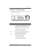
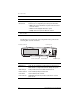
About the Product FEATURES OF THE DESKTOP UNIT This illustration shows the front of the Campus-RS Desktop Unit and the following table describes its features. HDSL LED LCD Menu buttons CAMPUS RS HDSL Next Test Escape Enter Port Port LED Test LED Feature Function HDSL LED Indicates the status of the HDSL link.
About the Product Feature Function LCD Displays configuration menu options and status information. Menu buttons Provide access to configuration options and system information: • Next scrolls to the next LCD menu or option at the same level of the menu structure. • Enter selects the displayed LCD menu or option. • Escape returns to the previous LCD menu selection. (a) To acknowledge a minor alarm, press and hold the Escape button on the front panel for three seconds.
About the Product HDSL REACH AND TRANSMISSION RATE There are four components that determine the maximum transmission rate and loop length of the HDSL line: • the wire gauge of the line • the condition of the line (presence of bridge taps, splices, and so on) • whether the line uses one or two loops • the amount of noise on the line The following charts on page 1-6 through page 1-7 show the maximum loop length over the range of HDSL transmission rates for 26 AWG (.40 mm), 24 AWG (.51 mm), 22 AWG (.
About the Product 1 Campus-RS, Maximum Reach vs Rate 26 AWG (0.40 mm) 8.00 25.0 7.00 Reach (km) 5.00 15.0 4.00 10.0 3.00 Reach (kft) 20.0 6.00 2.00 5.0 1.00 2304/4608 2048/4096 1792/3584 1536/3072 1280/2560 1024/2048 768/1536 384/768 0.0 128/256 0.00 Data Rate, One Loop/Two Loops (kbps) 2 Campus-RS, Maximum Reach vs Rate 24 AWG (0.51 mm) 10.00 30.0 9.00 25.0 7.00 20.0 6.00 5.00 15.0 4.00 Reach (kft) Reach (km) 8.00 10.0 3.00 2.00 5.0 1.
About the Product 3 Campus-RS, Maximum Reach vs Rate 22 AWG (0.51 mm) 16.00 50.0 14.00 Reach (km) 10.00 30.0 8.00 20.0 6.00 Reach (kft) 40.0 12.00 4.00 10.0 2.00 0.0 2304/4608 2048/4096 1792/3584 1536/3072 1280/2560 1024/2048 768/1536 384/768 128/256 0.00 Data Rate, One Loop / Two Loops (kbps) 4 Campus-RS, Maximum Reach vs Rate 19 AWG (0.51 mm) 25.00 80.0 70.0 20.00 50.0 15.00 40.0 10.00 30.0 Reach (kft) Reach (km) 60.0 20.0 5.00 10.
About the Product 1-8 Campus-RS Desktop Unit User Manual
SETTING UP AND TESTING THE DESKTOP UNIT 2 This chapter describes how to install an interface card into the Campus-RS Desktop Unit, set basic configuration options, and test the HDSL link. Make sure the interface card you are installing is a Campus-RS interface card. The Campus-RS Desktop Unit is not compatible with previous versions of Campus interface cards.
Setting Up and Testing the Desktop Unit Install the NID on the HDSL line between the HDSL jack and the Telephone Company (Telco) demarcation point. Telco demarcation point HDSL line port NID HDSL jack Campus-RS Unit HDSL line ADC also suggests providing power line protection for critical circuits in high lightning areas. Use conditioned AC voltage, furnished through an Uninterruptible Power Supply (UPS), that is bonded to a good facilities ground.
Setting Up and Testing the Desktop Unit INSTALLING AN INTERFACE CARD You can install any ADC Campus-RS interface card into the Campus-RS Desktop Unit. To install the interface card: 1 Slide the card into the guide rails in the rear of the Desktop Unit. Desktop unit Guide rail Interface card CA MP US -R S 1 or 20 V 22 AC 0V @ 6 .2AAC@0H z Ma 50 x Hz CO NS OL E CF G FR AC TIO NA L V.3 5 LIN E 2 Gently press the card into place until it is seated firmly in the mating connector.
Setting Up and Testing the Desktop Unit • Extended Mode provides a wide range of HDSL transmission rates when the Desktop Unit is connected to another Campus-RS product. The following illustration shows the operating modes available for the possible Campus system configurations.
Setting Up and Testing the Desktop Unit SET THE HDSL OPERATING MODE AND TRANSMISSION RATE This section provides basic instruction for setting the HDSL Operating Mode and transmission rate. The actual steps depend on the interface card in the Desktop Unit. Refer to the interface card user manual for a description of configuration and implementation options.
Setting Up and Testing the Desktop Unit Standard Mode Configuration This section continues from Step 5 in the previous section to set a standard HDSL transmission rate. 1 If the Operating Mode is set to STANDARD, proceed to Step 3. Otherwise, press Enter. 2 Press Next until STANDARD displays, then press Enter. The LCD displays OPERATING MODE. 3 Press Next until HDSL RATE displays, then press Enter. 4 Press Next until the desired HDSL transmission rate displays, then press Enter.
Setting Up and Testing the Desktop Unit SET THE HDSL TRANSCEIVER MODE The Transceiver Mode option determines the hierarchy of the two Campus units when attempting to establish an HDSL link. There are three settings: • If a unit is set to Master, it initiates the HDSL link. The other Campus unit must be set to Slave or Auto. • If a unit is set to Slave, it waits for the other Campus unit to initiate the HDSL link. The other unit must be set to Master or Auto.
Setting Up and Testing the Desktop Unit It is recommended that the Transceiver Mode be set as follows to avoid any link startup or operation problems: • Campus-RS = MASTER • Campus E1/T1/768 = SLAVE If one or both units are already set to AUTO and the HDSL link is active, disconnect the HDSL link, change the settings as recommended, and reconnect the link. This will assure the link integrity on any subsequent startups. This situation does not apply to a circuit with two Campus-RS units.
Setting Up and Testing the Desktop Unit TEST THE HDSL PORT It is recommended that you test all Desktop Units at your location prior to installing units at a remote site. This minimizes additional trips to the remote site to troubleshoot problems. It is also possible to test a Desktop Unit with a Line Unit installed in a Campus-Star chassis. This requires creating a cable to connect the HDSL port on the Desktop Unit to the port on the Campus-Star.
Setting Up and Testing the Desktop Unit Desktop units CF G FR AC TI O ON NA AL L V.35 C GF .V 53 RF CA IT NO LA CO NS OL E LIN E HDSL cable 4 Connect one end of the black HDSL cable that came with the Desktop Unit to the LINE port on the back panel of one unit. 5 Connect the other end of the cable to the LINE port on the of second unit. The units attempt to synchronize the HDSL link. Synchronization may take up to 60 seconds or several minutes, depending on the interface card.
Setting Up and Testing the Desktop Unit TEST THE DATA PORT The data port of most Campus interface cards can be tested prior to installing the Desktop Unit in a remote location. This minimizes the chance of having to make additional trips to the remote site to troubleshoot problems. To test the data port, initiate a loopback from the local data port toward the local data port. Refer to the interface card user manual for instructions on initiating loopbacks.
Setting Up and Testing the Desktop Unit 2-12 Campus-RS Desktop Unit User Manual
DEPLOYING THE DESKTOP UNIT 3 This chapter describes how to deploy the Desktop Unit into its operating location. SET UP THE HDSL LINE Before you can connect the Campus-RS Desktop Unit to the HDSL line, you must first connect and install the RJ-45 modular jack that came with the Desktop Unit. You need needle-nosed pliers and a No. 2 standard screwdriver to complete these steps. You can connect the Desktop Unit to two different types of HDSL lines: • Dual-Loop uses two pairs of copper wire.
Deploying the Desktop Unit Dual-Loop Line A dual-loop line requires two pairs of wire. Use the same wiring for both the local and remote sites. A dual-loop line is compatible with all the standard modes and extended modes supported by the interface card. 3-2 1 Separate the two halves of the RJ-45 modular jack. 2 Connect the Tip wire for HDSL loop 1 to pin 1 of the jack. 3 Connect the Ring wire for HDSL loop 1 to pin 2 of the jack. 4 Connect the Ring wire for HDSL loop 2 to pin 4 of the jack.
Deploying the Desktop Unit Single-Loop Line A single-loop line requires a single pair of wire. Use the same wiring for both the local and remote sites.
Deploying the Desktop Unit CONNECT THE DESKTOP UNIT TO THE HDSL LINE To finish setting up and connecting to the HDSL line: 1 Place the RJ-45 jack where you are going to install it and push the excess wire into the punch box. 2 Use the two provided screws to screw the jack to the wall. 3 Snap the jack cover into place. Campus-RS Desktop Unit CF G FR RJ-45 Modular Jack AC T IO NA L V.3 5 CA MP US -R S 1 or 20 V 22 AC 0V @ 6 .
Deploying the Desktop Unit COMPLETE SYSTEM INSTALLATION To continue the installation of your Campus-RS system and ready it for use: 1 Install the remote unit. This may be an interface card installed in another Campus-RS Desktop Unit or an interface card and Campus-RS Line Unit installed in a Campus-Star chassis. 2 Connect the remote unit cables according to the instructions in the Campus-Star or Campus-RS Desktop Unit documentation.
Deploying the Desktop Unit 3-6 Campus-RS Desktop Unit User Manual
TECHNICAL SPECIFICATIONS A HDSL Line Signal Format E1 Full Duplex 1040 kbps 2B1Q Line Code (two pair) T1 (default) Full Duplex 784 kbps 2B1Q Line Code (two pair) 768 Full Duplex 784 kbps 2B1Q Line Code (one pair) Transmit Signal Power +13.5 dBm (±1 dBm) Connector RJ-45 Return Loss 20 dB, 40 kHz to 200 kHz Loop Provisioning Loss E1 35 dB at 260 kHz at 135Ω T1 35 dB at 196 kHz at 135Ω 768 35 dB at 196 kHz at 135Ω One-Way Transmission Delay Less than 300 microseconds Physical Height 2.
Technical Specifications Electrical Power Input AC Version 120 Vac at 60 Hz or 220 Vac at 50 Hz DC Version -18 Vdc to -60 Vdc DC input was evaluated from -18 Vdc to -72 Vdc. To stay in compliance with Safety Regulations under EN60950, the DC input must not exceed a magnitude of -60 Vdc.
THE DOCUMENTATION SET B This table describes the user manuals and guides in the Campus-RS documentation set. Document Description Campus-Star User Manual Contains instructions for setting up and using a Campus-Star. The manual includes instructions for installing Line Units and interface cards into the Campus-Star chassis. Campus-RS Line Unit User Manual Describes the features of the Campus-RS Line Unit and provides installation instructions.
The Documentation Set B-2 Campus-RS Desktop Unit User Manual
PRODUCT SUPPORT C ADC Customer Service Group provides expert pre-sales and post-sales support and training for all its products. Technical support is available 24 hours a day, 7 days a week by contacting the ADC Technical Assistance Center (TAC). Sales Assistance 800.366.3891 extension 73000 (USA and Canada) 952.917.3000 Fax: 952.917.3237 • Quotation Proposals Systems Integration 800.366.3891, extension 73000 (USA and Canada) 952.917.
Product Support Online Technical Publications • www.adc.com/library1/ Product Return Department 800.366.3891 ext. 73748 or 952.917.3748 Fax: 952.917.3237 Email: repair&return@adc.com • ADC Return Material Authorization (RMA) number and instructions must be obtained before returning products. All telephone numbers with an 800 prefix are toll-free in the USA and Canada. MIBS ADC Management Information Bases (MIBs) are available through the Internet at http://www.adc.com.
CERTIFICATION AND WARRANTY FCC COMPLIANCE This equipment has been tested and found to comply with the limits for a Class A digital device, pursuant to Part 15 of the FCC Rules. These limits are designed to provide reasonable protection against harmful interference when the equipment is operated in a commercial environment.
ADC DSL Systems, Inc. 14402 Franklin Avenue Tustin, CA 92780-7013 Tel: 714.832.9922 Fax: 714.832.9924 Technical Assistance Tel: 800.638.0031 Tel: 714.730.3222 Fax: 714.730.2400 ISO 9001/TL 9000 DNV Certification, Inc.