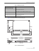
ADCP-90-328 • Issue 2 • November 2005 FPL Series Termination/Splice Panel User Manual) 2 8 14 20 26 3 32 9 42 15 48 21 54 27 4 60 33 10 66 38 16 72 44 22 50 28 5 56 34 11 62 39 17 68 45 23 51 29 6 57 35 12 63 40 18 69 46 24 52 30 58 36 64 41 70 47 53 59 65 42 71 48 54 60 66 72 17807-A FPL Termination/Splice Panel Content Page INTRODUCTION . . . . . . . . . . . . . . . . . . . . . . . . . . . . . . . . . . . . . . . . . . . . . . . . . . . . . . . . . . . . . . . .
ADCP-90-328 • Issue 2 • November 2005 Content (continued) 5.6 Page Installing FOT Patch Cords . . . . . . . . . . . . . . . . . . . . . . . . . . . . . . . . . . . . . . . . . . . . . . . . . . . . . . . . . . 28 5.6.1 Interconnect Application . . . . . . . . . . . . . . . . . . . . . . . . . . . . . . . . . . . . . . . . . . . . . . . . . . . . 28 5.6.2 Cross-Connect Application . . . . . . . . . . . . . . . . . . . . . . . . . . . . . . . . . . . . . . . . . . . . . . . . . . .
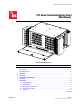
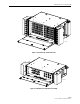
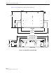
ADCP-90-328 • Issue 2 • November 2005 Figure 1 shows an example of a termination only panel, the 72 position model. Other models have analogous features.
ADCP-90-328 • Issue 2 • November 2005 • Cable Clamp Cover—protects cable at entry to the panel (not present on 12 and 24 position panels). • Vertical Cable Guide—(one on each side) is a metal cable retainer designed to provide cable management by confining and directing patch cords to and from the panel and along the frame on which the panel is installed. • Patch Cord Designation Card—is a laminated card fastened to the inside of the panel front door.
ADCP-90-328 • Issue 2 • November 2005 1 7 13 19 25 31 2 37 8 43 14 20 26 32 3 38 9 49 44 15 55 61 21 67 27 73 33 4 39 10 79 50 45 16 85 56 91 62 22 68 28 74 34 5 40 11 51 46 17 80 86 57 92 63 23 69 29 75 35 6 41 12 81 52 47 18 87 58 93 64 24 70 30 76 36 42 82 53 48 88 59 94 65 71 77 83 54 89 60 95 66 72 78 84 90 96 17815-A Figure 3.
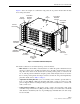
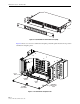
ADCP-90-328 • Issue 2 • November 2005 20973-A Figure 5. 12/24 Position FPL Termination Panel (1RU) Figure 6 shows a rear view of a termination and splice panel. The panel shown is the 72 position termination and splice panel. SPLICE AREA INTERNAL PIGTAIL 17819-A SPLICE TRAY OPTIONAL LOCK MOUNT REMOVABLE REAR ACCESS DOOR Figure 6. FPL Termination and Splice Panel Page 6 © 2005, ADC Telecommunications, Inc.
ADCP-90-328 • Issue 2 • November 2005 The front side of the 72 position termination and splice panel is identical to the termination only panel shown in Figure 1. In general, the termination components of any FPL termination and splice panel are identical to the termination components of the panel’s termination and splice panel counterpart. Only the splice components are different. Figure 6 on the preceding page shows the typical components unique to the splice function of a termination and splice panel.
ADCP-90-328 • Issue 2 • November 2005 2 ACCESSORIES The following accessory items may be ordered separately for FPL panels: • Single and dual splice trays (for types, see Splice Type in Table 1 below) • Additional kits for clamping and grounding cables • Key locks for front and rear doors • Buildout attenuators (ST and biconic) • Bulkhead attenuators (ST, SC, D4, FC, and biconic) 3 SPECIFICATIONS AND DIMENSIONS Table 1 lists specifications for the FPL modules. Table 1.
ADCP-90-328 • Issue 2 • November 2005 Table 1. FPL Modules Specifications PARAMETER SPECIFICATION 48/72/96 Position Panel (5RU) Dimensions (H x W x D) 8.7.0 inch x 21.9 in. x 12.0 in. (22.1 cm x 56.7 cm x 30.5 cm) Capacity 48, 72, or 96 termination positions LX.5© and LC connectors double the termination capacity 144 Position High Density Panel (5RU) Dimensions (H x W x D) Depth with rear door splice deck open 8.7.0 inch x 21.9 in. x 15.0 in. (22.1 cm x 56.7 cm x 38.1 cm) 23.0 inch (58.
ADCP-90-328 • Issue 2 • November 2005 Figure 9 shows dimensions of the 24 position 3RU panel. 12.0 IN. (30.5 CM) 5.0 IN. (12.7 CM) TOP VIEW 16.4 IN. (41.7 CM) 21.9 IN. (55.5 CM) 22.32 IN. (56.7 CM) 23-IN. RACK MOUNT (58.4 CM) 18.32 IN. (46.5 CM) 19-IN. RACK MOUNT (48.3 CM) 4.0 IN. (10.2 CM) 2.25 IN. (5.7 CM) 5.0 IN. (12.7 CM) FRONT VIEW Figure 9. Panel Dimensions (24 Position 3RU) Page 10 © 2005, ADC Telecommunications, Inc.
ADCP-90-328 • Issue 2 • November 2005 Figure 10 shows dimensions of the 48/72/96 position panel. 12.0 IN. (30.5 CM) 5.0 IN. (12.7 CM) TOP VIEW 16.4 IN. (41.7 CM) 21.9 IN. (55.5 CM) 22.32 IN. (56.7 CM) 23-IN. RACK MOUNT (58.4 CM) 18.32 IN. (46.5 CM) 19-IN. RACK MOUNT (48.3 CM) 8.7 IN. (22.1 CM) 4.0 IN. (10.2 CM) 2.25 IN. (5.7 CM) 5.0 IN. (12.7 CM) FRONT VIEW 17821-A Figure 10. Panel Dimensions (48/72/96 Position) Page 11 © 2005, ADC Telecommunications, Inc.
ADCP-90-328 • Issue 2 • November 2005 Figure 11 shows dimensions of the 144 position high density panel 15.0 IN. (38.1 CM) 5.0 IN. (12.7 CM) TOP VIEW 16.4 IN. (41.7 CM) 21.9 IN. (55.5 CM) 22.32 IN. (56.7 CM) 23-IN. RACK MOUNT (58.4 CM) 18.32 IN. (46.5 CM) 19-IN. RACK MOUNT (48.3 CM) 8.7 IN. (22.1 CM) 4.0 IN. (10.2 CM) 2.25 IN. (5.7 CM) 5.0 IN. (12.7 CM) FRONT VIEW Figure 11. Panel Dimensions (144 Position) Page 12 © 2005, ADC Telecommunications, Inc.
ADCP-90-328 • Issue 2 • November 2005 4 APPLICATION The FPL Series Termination/Splice Panel is designed for use in central offices, remote offices, and in local area networks (LANs) that use a fiber optic cable system.
ADCP-90-328 • Issue 2 • November 2005 FOT EQUIPMENT FOT EQUIPMENT CONNECTOR PANEL FOT EQUIPMENT FOT EQUIPMENT PATCH CORDS BULKHEAD ADAPTER FOT EQUIPMENT CROSS-CONNECT PATCH CORDS OSP CABLE OSP CONNECTOR PANEL BULKHEAD ADAPTER PIGTAIL SPLICE 2763-B Figure 13. Cross-Connect Application 5 INSTALLATION Installation will vary depending on how the panel was outfitted in the factory and how it will be used.
ADCP-90-328 • Issue 2 • November 2005 COMPRESS RELEASE TABS COMPRESS RELEASE TABS ROTATE AND SNAP INTO SLOT ROTATE AND SNAP INTO SLOT COMPRESS RELEASE TABS COMPRESS RELEASE TABS 1 17846-A 2 Figure 14. Example of Installing Adapters 5.2 Installing Pigtails Pigtails may be installed in any FPL panel (including termination only panels) to utilize the rear area of the panel for splicing.
ADCP-90-328 • Issue 2 • November 2005 17825-A Figure 15. Connector Numbers on Rear of 72 Position Bulkhead 4. Route the pigtails within the panel as shown in Figure 16 (12/24 position 1RU panel), Figure 17 (24 position 3RU panel), Figure 18 (48/72/96 position panel), or Figure 19 (144 position panel). 5. Continue installing the pigtails in groups of 12 until all of the pigtails are labeled, connected, and routed to the splice area.
ADCP-90-328 • Issue 2 • November 2005 LEFT SIDE PIGTAILS (AS VIEWED FROM REAR) RIGHT SIDE PIGTAILS (AS VIEWED FROM REAR) KURLYLOCKS OR FANNING TREE (ATTACHED TO TOP OF CHASSIS) OSP CABLE CLAMP 17920-A TOP VIEW (SHOWN WITH TOP OF CHASSIS REMOVED) Figure 17.
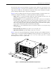
ADCP-90-328 • Issue 2 • November 2005 TOP VIEW (SHOWN WITH TOP OF CHASSIS REMOVED) LEFT SIDE PIGTAILS (AS VIEWED FROM REAR) RIGHT SIDE PIGTAILS (AS VIEWED FROM REAR) PIGTAILS 17910-A Figure 19. Pigtail Routing (144 Position High Density Panel Shown) 5.3 Mounting the Panel on the Rack Installation always requires mounting the panel on a rack. Page 18 © 2005, ADC Telecommunications, Inc.
ADCP-90-328 • Issue 2 • November 2005 The panel can be mounted in either a 19- or 23-inch EIA or WECO equipment rack with either a 4-inch or 5-inch recess. The panel is shipped with the mounting brackets positioned for installation in a 19-inch rack with a 5-inch recess. For other mounting configurations, the brackets must be removed and reinstalled in a different orientation. Use the following procedure to mount the panel on the rack: 1.
ADCP-90-328 • Issue 2 • November 2005 Typically, only one cable is installed per panel. The cable clamp can be installed on either side. A grounding lug is included with each clamp for grounding OSP cables that have metallic strength members or metallic sheaths. Allow a fiber service loop of at least 8 feet (2.5 meters) when stripping the sheath off the cable. This will provide sufficient length for routing the buffer tubes within the FPL panel and for splicing.
ADCP-90-328 • Issue 2 • November 2005 OUTSIDE PLANT CABLE GROMMET 60 YOKES 66 72 CABLE CLAMP COVER 56 62 68 57 63 #6 - 32 x 1.375-IN. SCREWS 69 58 64 70 REAR PROTECTIVE PLATE 59 65 71 60 66 72 17828-A #6 - 32 x 0.25-IN. SCREWS Figure 21. Cable Clamp Assembly (Top Entry) Note: Rear Protective Plate shown in these figures is not used on 24 position panel. 60 66 72 56 62 68 57 63 YOKES 69 58 64 #6 - 32 x 0.25-IN.
ADCP-90-328 • Issue 2 • November 2005 5. A grounding lug is provided for grounding metallic sheaths and metallic core members. Use the nut and screw provided to fasten the grounding lug to the chassis at the point shown in Figure 23. If the sheath bonding kit was installed, connect a bonding wire between the connector stud and the lug. If the cable has a metallic core member, insert the core member into the lug and tighten. 6.
ADCP-90-328 • Issue 2 • November 2005 In a typical installation, the methods and procedures that will be used for splicing are determined by local practice. Use the following procedure to organize the pigtails and buffer tubes for splicing and to store completed splices: Danger: Infrared radiation is invisible and can seriously damage the retina of the eye. Do not look into the optical bulkhead of an operational transmitter or into the receiver end of an active fiber.
ADCP-90-328 • Issue 2 • November 2005 LEFT SIDE PIGTAILS (AS VIEWED FROM REAR) RIGHT SIDE PIGTAILS (AS VIEWED FROM REAR) KURLYLOCKS OR FANNING TREE (ATTACHED TO TOP OF CHASSIS) OSP CABLE CLAMP 17920-A TOP VIEW (SHOWN WITH TOP OF CHASSIS REMOVED) Figure 25.
ADCP-90-328 • Issue 2 • November 2005 TOP VIEW (SHOWN WITH TOP OF CHASSIS REMOVED) LEFT SIDE PIGTAILS (AS VIEWED FROM REAR) RIGHT SIDE PIGTAILS (AS VIEWED FROM REAR) OSP CABLE CLAMP PIGTAILS BUFFER TUBES 17909-A Figure 27. Right Cable Exit (Left as Viewed from Rear), 144 Position Panel Page 25 © 2005, ADC Telecommunications, Inc.
ADCP-90-328 • Issue 2 • November 2005 TOP VIEW (SHOWN WITH TOP OF CHASSIS REMOVED) LEFT SIDE PIGTAILS (AS VIEWED FROM REAR) RIGHT SIDE PIGTAILS (AS VIEWED FROM REAR) OSP CABLE CLAMP PIGTAILS BUFFER TUBES 17918-A Figure 28. Left Cable Exit (Right as Viewed from Rear),144 Position Panel 6. Lay the bundle(s) across the top of the splice tray as shown in the figures and determine the point at which each pigtail and cable subunit should be attached to the splice tray.
ADCP-90-328 • Issue 2 • November 2005 BUFFER TUBES SECURE PIGTAILS AND BUFFER TUBES TO SPLICE TRAY WITH TIE WRAPS 2776-A Figure 29. Routing Bundles into Splice Tray 7. Mark each buffer tube and pigtail to indicate the attachment point to the splice tray. Make sure approximately 2 feet (61 cm) of fiber are left beyond the attachment point for splicing. 8. Remove the splice tray from the FPL panel and uncoil the bundles from the radius limiters. 9.
ADCP-90-328 • Issue 2 • November 2005 17832-A Figure 30. Splice Tray Mounted in 24 Position FPL Panel 18. Close and latch front and rear covers. 5.6 Installing FOT Patch Cords In both interconnect and cross-connect applications, FOT equipment patch cords are installed between the FOT equipment and the FLP panel. The following sections describe the installation procedure to use based on the application. Danger: Infrared radiation is invisible and can seriously damage the retina of the eye.
ADCP-90-328 • Issue 2 • November 2005 1. Connect the FOT equipment patch cord to the appropriate bulkhead adapter/receptacle at the front side of the FPL panel as shown in Figure 31. Note: If using biconic or ST receptacles, install a 0 dB build-out to permit installation of the patch cord. 2. Use the retainers at the left and right sides of the FPL panel to route patch cords away from the front side of the FPL panel. 3. Route patch cord from the FPL panel to the FOT equipment. 4.
ADCP-90-328 • Issue 2 • November 2005 2. Route the patch cord from the FOT equipment to the rear side of the FPL panel. 3. Connect the FOT equipment patch cord to the appropriate bulkhead adapter/receptacle within the FPL panel as shown in Figure 32. Note: If using biconic or ST receptacles, install a 0 dB build-out to permit installation of the patch cord. 4. Coil excess patch cord slack around the radius limiters on the bottom of the FPL panel. 5.
ADCP-90-328 • Issue 2 • November 2005 1. Open the front cover of both the FOT equipment and OSP-dedicated FPL panel. Danger: Infrared radiation is invisible and can seriously damage the retina of the eye. Do not look into the optical bulkhead of an operational transmitter or into the receiver end of an active fiber.
ADCP-90-328 • Issue 2 • November 2005 7 CUSTOMER INFORMATION AND ASSISTANCE PHONE: U.S.A.
ADCP-90-328 • Issue 2 • November 2005 APPENDIX A: SHIELD CONNECTOR INSTALLATION This appendix provides the procedures for installing Scotchlok 4460 Shield Connectors, which are manufactured by the 3M Company and utilized in the Fiber Management Panel. The shield connector kit provides a means for grounding cables that have a metallic shield. Use the following procedure to install each kit: 1. The shield connector kit is comprised of the components shown in Figure 34.
ADCP-90-328 • Issue 2 • November 2005 Reproduced by permission of 3M Company, from 3M Instruction Bulletin, Issue 1, dated February 1985, Number 43-7018-2209-9. 3. Make a one-inch cut in the cable sheath opposite the point at which the connector will be attached as shown in Figure 36. 1.0 IN. (25 mm) 9174-A Figure 36. Cutting Cable Sheath 4. If installing single shield cable, insert connector base between shield and core wrap.