
FPL Series Termination/Splice Panel ADCP-90-328 User Manual

ADCP-90-328 • Issue 2 • November 2005
Page 13
© 2005, ADC Telecommunications, Inc.
4 APPLICATION
The FPL Series Termination/Splice Panel is designed for use in central offices, remote offices,
and in local area networks (LANs) that use a fiber optic cable system. The panel provides a
common point for performing any of the following functions:
• Terminating OSP or IFC cables
• Terminating Fiber Optic Terminal (FOT) equipment patch cords
• Storing excess FOT equipment patch cord length
• Connecting FOT equipment with OSP cables
• Mounting and protecting splices
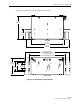
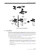
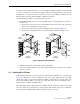
When used with OSP cable, the FPL panel may be used for either interconnect or cross-connect
applications. Figure 12 and Figure 13 provide a pictorial comparison of these two types of
applications. As shown, in both interconnect and cross-connect applications, the OSP cable is
terminated on the rear side of the panel and spliced to the internal pigtails within the panel.
Also, in both applications, the pigtails are connected to the rear side of the adapters on the
termination bulkhead. The applications differ in what occurs on the front side of the panel.
• In an interconnect application, shown in Figure 12, patch cords from the FOT equipment
are connected directly to fibers spliced and terminated on the rear side of the same panel.
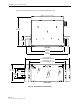
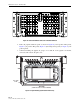
• In a cross-connect application, shown in Figure 13, patch cords from the FOT equipment
are terminated on one panel and the fibers are spliced and terminated on a second panel,
with cross-connect patch cords providing links between the two panels. This two-panel
arrangement provides more flexibility in testing and patching optical circuits than is
provided by a single panel arrangement.
Figure 12. Interconnect Application
FOT EQUIPMENT
FOT EQUIPMENT
FOT EQUIPMENT
OSP CONNECTOR PANEL
FOT EQUIPMENT
PATCH CORDS
SPLICE
BULKHEAD
ADAPTER
OSP
CABLE
PIGTAIL
2762-B