
FPL Series Termination/Splice Panel ADCP-90-328 User Manual

ADCP-90-328 • Issue 2 • November 2005
Page 20
© 2005, ADC Telecommunications, Inc.
Typically, only one cable is installed per panel. The cable clamp can be installed on either side.
A grounding lug is included with each clamp for grounding OSP cables that have metallic
strength members or metallic sheaths.
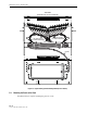
Allow a fiber service loop of at least 8 feet (2.5 meters) when stripping the sheath off the cable.
This will provide sufficient length for routing the buffer tubes within the FPL panel and for
splicing. After entry, the buffer tubes are routed to the splice tray. The splice tray mounts on the
bottom of the FPL panel.
Use the following procedure to secure the OSP cable at the fiber entry point and to route the
optical fibers into the FPL panel:
1. Route the OSP cable to the selected entry opening at the side of the FPL panel.
2. Strip back the cable sheath approximately 96 inches (2.5 meters) to expose the optical
fibers. Follow the cable manufacturer’s recommendations when stripping the sheath.
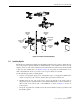
3. Determine the correct clamp and grommet combination required to secure the cable to the
panel. A rubber clamp and three grommets of various sizes are provided. Select a grommet
that when placed around the cable, has a gap of nearly zero to 0.30 inches (0.76 cm). If the
cable diameter is greater than 0.70 inches (1.78 cm), only the rubber clamp is required.
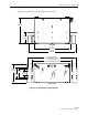
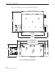
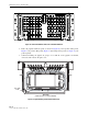
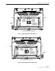
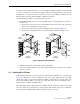
4. Use the rubber clamp, clamp cover, grommet (if required), and two screws to secure the
cable end to the side of the FPL panel chassis, as shown in Figure 21 for a top entry cable
and in Figure 22 for a bottom entry cable.
Note: Cables may enter the FPL panel from either the top or bottom and may be clamped
to either the left or right side
Note: If the cable is filled with water blocking compound, the cable end must be sealed to
prevent leakage. A blocking kit (accessory item) is required for sealing the cable end.
Install the kit according to the instructions provided with the kit.
Note: If cable has a metallic sheath, a special connector is provided with the cable
grounding kit (accessory item FIP-ACC-GK) for grounding the sheath. Refer to Appendix
A for the installation procedures for ScotchLok 4460 Shield Connectors which are
manufactured by the 3M Company.
Note: The Rear Protective Plate, identified in the figures, is not used with the 24 position
panel. The plate is not included in the cable clamp kit.