HiGain USER MANUAL H2TU-C-231 List 2 Line Unit Product Catalog: H2TU-C-231-L2 CLEI: VACJDLYE 2
LTPH-UM-1109-01, Issue 1 Revision History of This Practice Revision Release Date Revisions Made 01 January 9, 2002 Initial release. Copyright January 9, 2002 © 2002 ADC DSL Systems, Inc. All rights reserved. Trademark Information ADC is a registered trademark of ADC Telecommunications, Inc. HiGain is a registered trademark of ADC DSL Systems, Inc.
LTPH-UM-1109-01, Issue 1 Using This Manual USING THIS MANUAL The following conventions are used in this manual: • Monospace type indicates screen text. • Keys you press are indicated by small icons such as Y or ENTER . Key combinations to be pressed simultaneously are indicated with a plus sign as follows: CTRL + ESC . • Items you select are in bold. • Three types of messages, identified by icons, appear in text. Notes contain information about special circumstances.
Inspecting Shipment iv LTPH-UM-1109-01, Issue 1 January 9, 2002 H2TU-C-231 List 2
LTPH-UM-1109-01, Issue 1 Table of Contents TABLE OF CONTENTS Overview ____________________________________________________________________________ 1 Features ..............................................................................................................................................1 Compatibility .....................................................................................................................................2 Applications ..............................................
Table of Contents LTPH-UM-1109-01, Issue 1 Testing _____________________________________________________________________________ 40 System Alarms................................................................................................................................. 40 Alarm Option for Digital Loop Carrier (DLC) Feed ........................................................ 41 Retiring System Alarms ....................................................................................................
LTPH-UM-1109-01, Issue 1 List of Figures LIST OF FIGURES 1. H2TU-C-231 List 2 Front Panel.......................................................................................................................3 2. Installing the H2TU-C-231 List 2 into a Shelf.................................................................................................7 3. Logon Screen..........................................................................................................................................
List of Tables LTPH-UM-1109-01, Issue 1 LIST OF TABLES 1. Front-Panel Description ................................................................................................................................... 4 2. Front-Panel Display Messages......................................................................................................................... 5 3. Navigational Keys for the Maintenance Terminal Screens ........................................................................... 11 4.
LTPH-UM-1109-01, Issue 1 Overview OVERVIEW The H2TU-C-231 List 2 line unit is the Central Office (CO) side of a T1 transmission system. The HiGain™ HDSL2 product family is fully compliant with the HDSL2 standard ANSI T1.418-2000. Providing full-rate T1 access using just a single copper pair, HDSL2 is a cost-effective solution that offers an open architecture. The open architecture inherent in HDSL2 guarantees interoperability allowing simple and economic accommodation of network growth.
Overview LTPH-UM-1109-01, Issue 1 – Remote provisioning – Selectable loopback activation codes • Additional (Loopback Timeout) LBTO settings of 8 hours and 24 hours • Compatible with Small Cross-Section Shelf (SXSS) and equipment DS1 is used throughout this document to refer to either the remote unit’s DS1 interface or the line unit’s DSX-1 interface. COMPATIBILITY The H2TU-C-231 List 2 is designed to mount in 220 mechanics shelves.
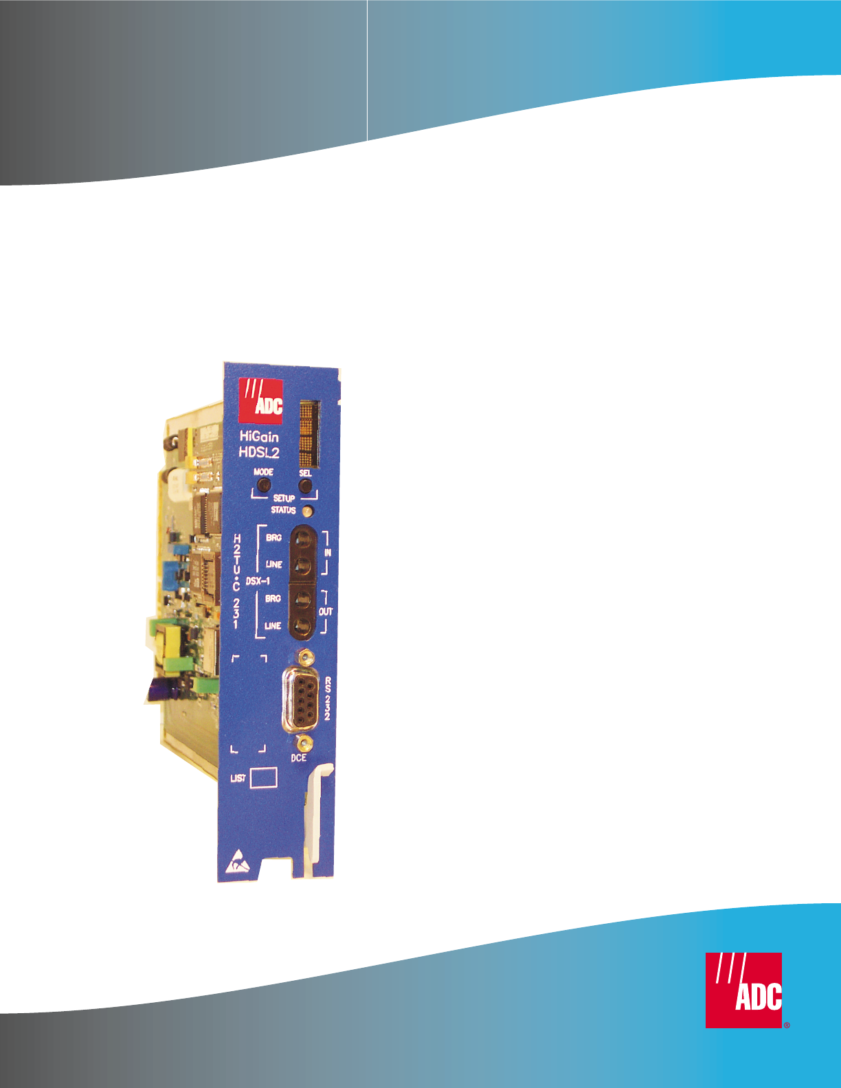
LTPH-UM-1109-01, Issue 1 Front Panel FRONT PANEL Figure 1 shows the H2TU-C-231 List 2 front panel. Table 1 on page 4 describes the front-panel components. For a list of front-panel display messages, refer to “Front-Panel Display Messages” on page 5. For pinout diagrams of the H2TU-C card-edge connector and craft port, refer to “Appendix A - Specifications” on page 54.
Front Panel LTPH-UM-1109-01, Issue 1 Table 1. Front-Panel Description Front-Panel Feature Function Front-panel display Displays four-character status, provisioning, and alarm system messages. The front-panel display illuminates when power is initially applied. To conserve power, the display only remains on for 5 minutes. Using the MODE or SEL pushbuttons reactivates the display and restarts the 5-minute timer. Refer to Table 2 on page 5 for a listing of the four-character messages.
LTPH-UM-1109-01, Issue 1 Front Panel Table 2 lists the front-panel display messages. The four-character display reports the code of a pertinent alarm, loopback, or diagnostic message and, in some cases, is followed by a second four-character message that modifies the first message with a value or current configuration setting. Table 2.
Front Panel LTPH-UM-1109-01, Issue 1 Table 2. Front-Panel Display Messages (Continued) Message Full Name Description NREM Network Remote Loopback DSX-1 signal is looped back to the network at the H2TU-R. RULB Remote Unit Loopback Dual loopback at the H2TU-R. SMJK Remote SmartJack Loopback DSX-1 signal is looped back to the network at the H2TU-R SmartJack module.
LTPH-UM-1109-01, Issue 1 Installation INSTALLATION Upon receipt of the equipment, inspect the contents for signs of damage. If the equipment has been damaged in transit, immediately report the extent of damage to the transportation company and to ADC. H2TU-C-231 HiG HLU ain -4 LIN 31 EU N IT CO Shelf Pa irG ain Figure 2. Installing the H2TU-C-231 List 2 into a Shelf When installing an H2TU-C 231 in a chassis, be sure to wear an antistatic wrist strap.
Installation LTPH-UM-1109-01, Issue 1 VERIFICATION Once the H2TU-C-231 is installed, verify that it is operating properly. To do this, monitor the following: • Status LED (see Figure 1 on page 3) • Status messages reported by the front-panel display (see Table 2 on page 5) Verification without an H2TU-R Remote Unit If there is no H2TU-R remote unit installed: 1 Verify that the H2TU-C powers up. The front-panel display illuminates and reports status messages.
LTPH-UM-1109-01, Issue 1 Provisioning PROVISIONING There are two methods for provisioning: • • Use the MODE and SEL pushbuttons on the front panel of the H2TU-C to: – Set system options – Reset the H2TU-C to its factory default settings for system options – Display system option settings (scroll mode) – Select system loopbacks Use a maintenance terminal (VT100 terminal or a PC running terminal emulation software) connected to the H2TU-C craft port (or to an HMU craft port) to access the maintena
Provisioning LTPH-UM-1109-01, Issue 1 Resetting to Factory Default Values All user options for the H2TU-C-231 List 2 (Table 6 on page 18) can be set to the factory default values using the MODE and SEL pushbuttons. To set the user options to their default values: 1 Press the SEL pushbutton for 6 seconds until the following message appears: DFLT NO 2 Press the SEL pushbutton while the DFLT NO message is displayed.
LTPH-UM-1109-01, Issue 1 Provisioning USING A MAINTENANCE TERMINAL Connecting to a Maintenance Terminal The craft port on the front panel allows you to connect the H2TU-C-231 to a maintenance terminal (ASCII terminal or PC running a terminal emulation program). Once connected to a maintenance terminal, you can access the maintenance, provisioning, and performance screens.
Provisioning LTPH-UM-1109-01, Issue 1 Most VT100 emulation programs support a print screen option. For Windows-based programs, such as Procomm or HyperTerminal, do the following: 1 Highlight the screen that you wish to print. 2 Click File, then Print. 3 In the Print dialog box, choose Selection as the Print Range. 4 Click OK to print. For printing procedures for other programs, contact the appropriate vendor.
LTPH-UM-1109-01, Issue 1 Provisioning Table 4. Logon Screen Menus (Continued) Press this key: To access this menu: R Rlogon/Rlogout Remote logon can be performed from the H2TU-C or H2TU-R. The screen displays “Rlogout” when the H2TU-C or H2TU-R is remotely logged on to the other unit at the end of the circuit. Remote logon from the H2TU-C will permit viewing of the H2TU-R and BERT Signal Generator configuration submenu. To log off from the remote unit, press R . “Rlogout” changes to “Rlogon”.
Provisioning 4 LTPH-UM-1109-01, Issue 1 Type the time in the format indicated (entering seconds is optional), then press ENTER . Setting Circuit ID Numbers The Inventory screen provides product information on all units in the system and allows setting of the circuit and unit identification numbers. Monitor Performance Event Log Config Inventory -------------------------Product Information Unit : H2TU-C H2TU-R Product : H2TU-C-231 H2TU-R-402 List : 2 1B Sw Ver. : 3.00 3.
LTPH-UM-1109-01, Issue 1 Provisioning Configuring the System The Config menu (Figure 6) allows you to make the following types of system configuration changes: • Standard options (Figure 7 on page 16) • ADC options (Figure 8 on page 16) • BERT Generator (Figure 29 on page 52) • Date and time (see “Setting Date and Time” on page 13) • Master clear (see “Clearing the History, Alarm, and Event Log Screens” on page 23) • Reset to factory default configuration (see “Resetting to Factory Default Valu
Provisioning Monitor LTPH-UM-1109-01, Issue 1 Performance Event Log Config Inventory Report Rlogon Help +----------------------+ | Standard Options -> | +---------------------------------------------------+ | Loopback Timeout (LBTO) : 60 min | | Loop Attenuation Threshold (LATT) [0-40]: 35 dB | | Margin Threshold (MARG) [0-15]: 4 dB | | DS1 Frame Formatting (FRMG) : AUTO | | DS1 Line coding (DS1) : AUTO | | H2TU-C Equalization (EQL) : EXT | | H2TU-R Line Buildout (RLBO) : 0 dB | | Alarm Pattern (ALMP)
LTPH-UM-1109-01, Issue 1 Provisioning Table 5 describes the Standard Config menu options and Table 6 on page 18 describes the ADC Config menu options. Selections in bold type indicate factory default settings. Table 5. Standard Config Menu Options Loopback Timeout Loop Attenuation Threshold Front-Panel Display Selection Code Description LBTO NONE Disables automatic time-out cancellation of all loopbacks. 20 Sets automatic cancellation of all loopbacks to 20 minutes after initiation.
Provisioning LTPH-UM-1109-01, Issue 1 Table 5. Standard Config Menu Options H2TU-R Line Buildout Front-Panel Display Selection Code RLBO Alarm Pattern See “Alarm Pattern (ALMP) Option” on page 20. ALMP H2TU-R TLOS Loopback TLOS Network Loopback Pattern H2TU-C-231 List 2 Standard Config Menu Options (Continued) Sets the DS1 receive level output toward the Customer Interface (CI). H2TU-R Line Buildout can only be set through the maintenance screens.
LTPH-UM-1109-01, Issue 1 Provisioning Table 6. H2TU-C-231 List 2 ADC Config Menu Options (Continued) Front Panel Display Code Selection Description DS1 BER Threshold See “DS1 BER (DBER) Option” on page 21. DBER ENA Enables the fixed 24-hour DS1 BER threshold. DIS Prevents the generation of a system alarm due to DS1 BER. HDSL2 BER Threshold See “HDSL2 BER Threshold (HBER) Option” on page 21 and “System Alarm Output Pins” on page 58.
Provisioning LTPH-UM-1109-01, Issue 1 H2TU-C Equalization (EQL) Option. The equalizer shapes the DS1 output signal of the H2TU-C to conform to a very specific pulse template when it arrives at the DSX-1 cross-connect point. The degree of pulse-shaping required is a function of the distance between the H2TU-C’s equipment bay and the DSX-1 panel. Thus, the equalizer has six discrete settings, in increments of 133 feet to cause the maximized separation of 655 feet. Alarm Pattern (ALMP) Option.
LTPH-UM-1109-01, Issue 1 Provisioning DS1 BER (DBER) Option. The DS1 BER alarm occurs when any of the DS1 or DSX-1 performance monitoring parameters listed in Table 7 exceed the counts shown for the 24-hour period between 12:00:00 AM through 11:59:59 PM. These thresholds correspond to a 10-6 BER. All PM counters clear to zero at 12:00:00 AM or when Master Clear is selected. Table 7.
Provisioning LTPH-UM-1109-01, Issue 1 Resetting to Factory Defaults Resetting the H2TU-C 231 to its original factory settings may cause interruption of service. To reset the H2TU-C-231 List 2 to its original factory defaults: C 1 Press 2 Use the 3 Press Y Monitor to select the Config menu. ↑ and ↓ arrow keys to select Set Factory Defaults, then press to reset the H2TU-C, or press Performance Event Log N ENTER . to cancel this action.
LTPH-UM-1109-01, Issue 1 Provisioning Clearing the History, Alarm, and Event Log Screens Select Master Clear to clear the History, Alarm, and Event Log screens after the system has been installed and is functioning properly. This removes miscellaneous data acquired during the startup session and ensures collection of accurate and meaningful data thereafter.
Monitoring System Activity and Performance LTPH-UM-1109-01, Issue 1 MONITORING SYSTEM ACTIVITY AND PERFORMANCE The HDSL2 system provides the following maintenance screens for monitoring system activity and assessing performance. • The Monitor screens provide a graphical representation of circuit activity and allow initiation of loopbacks. • The Performance screens provide current, 25-hour, 48-hour, and 31-day performance histories and a continuous alarm history.
LTPH-UM-1109-01, Issue 1 3 Monitoring System Activity and Performance To initiate a loopdown of all active loopbacks, press the SPACEBAR to select LPDN, then press ENTER or N . When prompted with the message: Are you sure (Y/N)?, press Y to initiate the loopdown or N to cancel. Table 8. Monitor Screen Descriptions Field Description Active loopback An active loopback is indicated on the lower third of the Monitor screen. Available loopbacks are indicated by gray text.
Monitoring System Activity and Performance LTPH-UM-1109-01, Issue 1 USING THE PERFORMANCE SCREENS TO VIEW PERFORMANCE DATA The Performance screens display: • CRC statistics for the HDSL2 or DS1 interface in 31-day, 48-hour, 25-hour, and current history reports. • Alarm statistics for the HDSL2 (Figure 23 on page 35) or DS1 interfaces (Figure 21 on page 33 and Figure 22 on page 33) on a continuous basis. To access the Performance history screens: P 1 Press to select the Performance screen.
LTPH-UM-1109-01, Issue 1 Monitor Monitoring System Activity and Performance Performance Event Log Config Inventory Report Rlogon Help H2TU-C DS1 48-Hour History (Page 1 of 4) -----------------------------------------------------------------------------Time CV-L ES-L SES-L UAS-L CV-P ES-P SES-P UAS-P *00:00 *01:00 *02:00 *03:00 *04:00 *05:00 *06:00 *07:00 *08:00 *09:00 *10:00 *11:00 14 10 10 12 10 10 0 0 Press: (N)ext Page, (P)revious Page, C(l)ear History ---------------------------------
Monitoring System Activity and Performance LTPH-UM-1109-01, Issue 1 Examples of current statistics screens are shown below. Figure 15 and Figure 16 show statistics for the DS1 interface at the remote unit and line unit, respectively. These screens report 1-day, 1-hour, and 15-minute statistics.
LTPH-UM-1109-01, Issue 1 Monitoring System Activity and Performance Table 9. Error Acronym Acronyms Used on the DS1 Performance History Screens Error Acronym Description Description CV-L Code Violation - Line Total BPV count. SES-P Severely Errored Seconds - Path Seconds with SES or CRC (ESF) ≥320 or FE (a) (SF) ≥8 (FT + FS). ES-L (b) Errored Seconds - Line Seconds with BPV ≥1. UAS-P Unavailable Seconds - Path A second of unavailability based on SES-P or AIS ≥1.
Monitoring System Activity and Performance LTPH-UM-1109-01, Issue 1 Performance History at the HDSL2 Interface The HDSL2 interface has 31-day, 48-hour, 25-hour, and current statistic screens for the H2TU-C. Figure 17 and Figure 18 below are examples of 31-day and 48-hour performance history screens. Figure 19 and Figure 20 on page 31 are examples of 25-hour and current statistics performance history screens.
LTPH-UM-1109-01, Issue 1 Monitor Monitoring System Activity and Performance Performance Event Log Config Inventory Report Rlogon Help H2TU-C HDSL2 25-Hour History (Page 1 of 9) ----------------------------------------------------------------------------Time CV ES SES UAS LOSWS *10:00 *10:15 *10:30 *10:45 11:00 11:15 11:30 11:45 12:00 12:15 12:30 12:45 14 0 0 10 0 0 10 0 0 12 0 2 10 0 0 Press: (N)ext Page, (P)revious Page, C(l)ear History ------------------------------------------------------
Monitoring System Activity and Performance Table 10.
LTPH-UM-1109-01, Issue 1 Monitoring System Activity and Performance Alarm History at the DS1 Interface The Alarm History screen reports DS1 statistics for the H2TU-C (Figure 21) and the H2TU-R (Figure 22) on a continuous basis. Table 11 on page 34 displays the types of alarms reported for both the H2TU-C and H2TU-R. Current alarms display in reverse video.
Monitoring System Activity and Performance LTPH-UM-1109-01, Issue 1 Table 11. Screen Alarm Front-Panel Alarm DS1 Alarm Descriptions Description H2TU-C DS1 ALARMS (see Figure 21 on page 33) LLOS (a) LLOS Line (Unit) Loss of Signal—Loss of the H2TU-C DSX-1 input signal. LAIS Line Alarm Indication Signal—Indicates an AIS (unframed all ones) pattern is being received at the H2TU-C DS1 input port.
LTPH-UM-1109-01, Issue 1 Monitoring System Activity and Performance Alarm History at the HDSL2 Interface The HDSL2 Alarm History screens report alarms at the H2TU-C and the H2TU-R. Figure 23 shows the H2TU-C HDSL2 alarm history and Table 12 below describes the alarms that are reported at the H2TU-C-231 or H2TU-R.
Monitoring System Activity and Performance LTPH-UM-1109-01, Issue 1 USING THE SYSTEM EVENT LOG TO TRACK EVENTS To view a running log of system events, press E to select the Event Log. The Event Log displays the date and time of the 100 most recent events (the most recent displayed first) and provides a description of each event. See Table 14 on page 39 for an alphabetical listing of all possible event log messages. • Press N or • Press T to return to the top of the log.
LTPH-UM-1109-01, Issue 1 Monitoring System Activity and Performance USING THE REPORT MENU The Report menu (Figure 25) provides screens containing status and performance monitoring data for line and remote units which can be downloaded to a file for analysis or future reference. Table 13 on page 38 describes the four types of reports provided by the Report menu. To select each individual report, do the following: O 1 Press to select Report menu.
Monitoring System Activity and Performance LTPH-UM-1109-01, Issue 1 Table 13.
LTPH-UM-1109-01, Issue 1 Monitoring System Activity and Performance Table 14.
Testing LTPH-UM-1109-01, Issue 1 TESTING This section provides information about front-panel system alarms, LOS and AIS response, OCT55 test procedure, and loopback testing. SYSTEM ALARMS Table 15 summarizes all possible HDSL2 system alarms in order of priority as they appear on the front panel. When multiple alarms occur, the front-panel display only reports the highest priority alarm. The alarm history screens display alarms also, but provide greater detail.
LTPH-UM-1109-01, Issue 1 Testing Table 15. Front-Panel System Alarms Summary (Continued) Front-Panel Message (a) Alarm Description To Inhibit xxx-DBER DS1 Bit Error Rate The DS1 BER has exceeded the set threshold limits of approximately 10-6. (xxx denotes either TUC or TUR. If TUC and TUR occur at the same time, then TUC displays.) Select DIS for the DBER system option. LOF Loss of Frame The DS1 input does not contain the ESF or SF frame pattern setting of the FRMG option.
Testing LTPH-UM-1109-01, Issue 1 Remote LOS and AIS Response Figure 26 shows the different ways the H2TU-R can respond to the network, depending on the configuration of the NLBP, TLOS, RDA, and ALMP configuration options described in Table 5 on page 17 and Table 6 on page 18.
LTPH-UM-1109-01, Issue 1 Testing LOOPBACK OPERATION HiGain HDSL2 has a family of loopback options for analyzing circuit functionality. The loopback signal is transmitted and returned to the sending device for comparison. This allows you to verify the integrity of the HDSL2 channels to the H2TU-C, the H2TU-C DSX-1 interface, and the DS1 channels to the customer.
Testing LTPH-UM-1109-01, Issue 1 Table 16. Summary of HiGain HDSL2 Loopback Codes and Activation Methods Method of Activation Loopback Code Description Test Set Craft Port MODE/SEL NLOC 1111000 4-in-7 DSX-1 signal is looped back to the network at the H2TU-C. X X X NREM 1110000 3-in-7 DSX-1 signal is looped back to the network at the H2TU-R. X X X CLOC 1111100 5-in-7 DS1 signal from the customer is looped back to the customer at the H2TU-R.
LTPH-UM-1109-01, Issue 1 Testing Special Loopback Commands In addition to the GNLB loopback command mode, a HiGain HDSL2 system can be configured for one of five special loopback command modes. These are selected from the maintenance terminal System Settings screen (see Table 6 on page 18) or by using the MODE and SEL pushbuttons (see Figure 28 on page 48).
Testing LTPH-UM-1109-01, Issue 1 Manual Loopback Session A manual loopback session allows you to select any one of the HiGain HDSL2 loopbacks listed in Table 16 on page 44 with the exception of SmartJack loopbacks, which can only be issued by inband commands. Setting the Loopback Time-Out Option Before initiating a loopback session, verify that the Loopback Time-Out parameter is set to the desired setting.
LTPH-UM-1109-01, Issue 1 4 • COL? = dual loopback at H2TU-C. • RUL? = dual loopback at H2TU-R. Testing Press SEL to activate the selected loopback. The previous loopback is terminated. Once a loopback is selected and activated, the loopback stays active until it times out (based on the LBTO setting). When a loopback times out, the display returns to the normal display mode.
Testing LTPH-UM-1109-01, Issue 1 4 Have the CO tester send the NLOC (4-in-7) inband loopup for 5 seconds. You should be able to observe the NLOC message on the front-panel display. (The Status LED on the front panel should be yellow, and the loopback mode should also be identified on the Monitor screen.) 5 Repeat Step 2. If the test passes, the problem is in the downstream direction. If it fails, the problem is in the upstream direction.
LTPH-UM-1109-01, Issue 1 Testing A1LB, A2LB, and A5LB Test Procedures Using the codes listed in Table 17, a network tester can activate NLOC or NREM loopbacks (or SMJK, if enabled). A tester at the customer premises can activate CLOC, CRG, or CREM loopbacks. All loopbacks shown in Table 17 can also be initiated from the H2TU-C-231 front-panel MODE and SEL pushbuttons (see “Setting Options through MODE and SEL” on page 9). Table 17.
Testing LTPH-UM-1109-01, Issue 1 To perform the A1LB, A2LB, and the A5LB loopback test procedures: 1 Send the inband Arming and NI LPBK code 11000 to the H2TU-C-231 for at least 5 seconds. 2 Monitor the output of the H2TU-C-231 for the return of the pattern. Return of the pattern indicates one of the following: 3 • The H2TU-R has looped up (if the SMJK Loopback option is enabled). • An external NID has looped up (if the SMJK Loopback option is disabled), and the H2TU-C and H2TU-R have been armed.
LTPH-UM-1109-01, Issue 1 Testing The Armed mode has an automatic time-out of 120 minutes, but this timer is reset to 120 for any of the following events: • Loopback terminates (manually or time-out) • Query • Alternate query • Far End activate • Another ARM command This timer is inhibited while any of the valid command codes are being sent. Once the codes are removed, the timer restarts at 120.
Testing LTPH-UM-1109-01, Issue 1 TESTING WITH H2TU-C BERT GENERATOR The H2TU-C BERT Generator screen allows transmission of a selected test signal from the H2TU-C towards either the network (NET) or customer (CPE). Bit error rates are calculated and display on the Monitor screen. It is not recommended using the Bit Error Rate Tester from the remote and line unit at the same time. C 1 Press to select the Config menu.
LTPH-UM-1109-01, Issue 1 Testing TESTING WITH H2TU-R BERT GENERATOR The H2TU-R BERT Generator screen allows transmission of a test signal from the H2TU-R towards either the network (NET) or customer (CPE). Bit error rates are calculated and display on the Monitor screen. R to logon remotely, then press C 1 Press 2 Use the 3 Use the arrow keys to select an option, then press the SPACEBAR to cycle through the settings. Refer to Table 19 on page 52 for a list of BERT Generator option settings.
Appendix A - Specifications LTPH-UM-1109-01, Issue 1 APPENDIX A - SPECIFICATIONS Power HDSL2 Span Voltage 0 or -180 Vdc ±5 Vdc CO Supply -48 Vdc nominal (-42.5 to -56.5 Vdc) (See “Power Consumption”, “Maximum Power Dissipation”, and “Maximum Current Drain” on page 55.) Electrical Protection Secondary surge and power cross-protection on HDSL2 ports. Requires external primary protection.
LTPH-UM-1109-01, Issue 1 Appendix A - Specifications POWER CONSUMPTION The three most important power parameters of an H2TU-C are its maximum power consumption, maximum power dissipation, and maximum current drain. Table 20 describes line-powered and locally powered circuits on 9 kft, 26 AWG loops. Table 20. H2TU-C-231 Power Parameters -48 Vdc Power Consumption (Watts) Heat Dissipation (Watts) -42.5 Vdc Current (mA) Maximum Maximum Maximum Line-powered 12.0 7.0 286.0 Locally powered 8.6 6.
Appendix A - Specifications LTPH-UM-1109-01, Issue 1 LOOP ATTENUATION, INSERTION LOSS, AND REACH Each loop has no more than 35 dB of loss at 196 kHz, with driving and terminating impedances of 135Ω, as shown in Table 21 below. This is equivalent to no more than 28 dB loop attenuation. Table 21. HDSL2 Reach Chart Cable Gauge Insertion Loss (a) at 196 kHz (dB/kft) Loop Attenuation (dB/kft) Maximum Reach (kft) Ω per kft 26/0.4 mm 3.88 3.1 9 83 24/0.51 mm 2.84 2.2 12 52 22/0.61 mm 2.18 1.
LTPH-UM-1109-01, Issue 1 Appendix A - Specifications H2TU-C-231 LIST 2 CARD-EDGE CONNECTOR Figure 31 shows the card-edge connectors on the H2TU-C-231 List 2. Active pins are highlighted in black. Figure 31. H2TU-C-231 List 2 Card-Edge Connector Network Management Control Bus The H2TU-C-231 provides a Network Management Control Bus on pin 46 of the card-edge connector. This allows the various ADC Management System protocols to manage the H2TU-C through the HMU-319 HiGain Management Unit.
Appendix A - Specifications LTPH-UM-1109-01, Issue 1 Fuse Alarm Pin 32 on the card-edge connector is a fuse alarm that is driven to -48 Vdc through a diode whenever the onboard fuse opens. System Alarm Output Pins Pins 20 and 21 on the card-edge connector (see Figure 31 on page 57) are the H2TU-C-231 System Alarm output relay contacts. The following notes apply to pins 20 and 21: • The H2TU-C-231 Status LED flashes red for the duration of a system alarm condition.
LTPH-UM-1109-01, Issue 1 Appendix B - Functional Operation APPENDIX B - FUNCTIONAL OPERATION ADC HDSL2 technology provides full-duplex services at standard DS1 rates over copper wires between an H2TU-C and an H2TU-R, which comprise one HiGain HDSL2 system. HiGain HDSL2 systems use Overlapped Pulse Amplitude Modulation Transmission with Interlocking Spectra (OPTIS) transceiver systems to establish full-duplex, 1.552 kbps data channels between the H2TU-C-231 and a remotely located H2TU-R.
Appendix C - Compatibility LTPH-UM-1109-01, Issue 1 APPENDIX C - COMPATIBILITY The HiGain system uses HDSL2 transmission technology as recommended by Bellcore TA-TSY-001210. HiGain HDSL2 complies with GR-63-CORE, TR-TSY-000499, and GR-1089-CORE.
LTPH-UM-1109-01, Issue 1 Appendix D - Product Support APPENDIX D - PRODUCT SUPPORT ADC Customer Service Group provides expert pre-sales and post-sales support and training for all its products. Technical support is available 24 hours a day, 7 days a week by contacting the ADC Technical Assistance Center (TAC). Sales Assistance 800.366.3891 extension 73000 (USA and Canada) 952.917.3000 Fax: 952.917.
Appendix E - Abbreviations LTPH-UM-1109-01, Issue 1 APPENDIX E - ABBREVIATIONS A DDS: Digital Data Service ACO: Alarm Cutoff DLC: Digital Loop Carrier ADSL: Asymmetric Digital Subscriber Line DS1: Digital Signal, Level 1 AIS: Alarm Indication Signal DSX-1: Digital Signal Cross-Connect, Level 1 ALM: Minor Alarm ALMP: Alarm Pattern AMI: Alternate Mark Inversion ANSI: American National Standards Institute AOR: Addressable Office Repeater ARM: Armed ASCII: American Standard Code fo
LTPH-UM-1109-01, Issue 1 Appendix E - Abbreviations LBPV: Local Bipolar Violation R LBTO: Loopback Timeout RAI: Remote Alarm Indication LED: Light Emitting Diode RAIS: Remote Alarm Indication Signal LLOS: Line (Unit) Loss of Signal RDA: Remote Disconnect Alarm LOS: Loss of Signal RLBO: H2TU-R Line Buildout LOSW: Loss of Sync Word RLOS: Remote (Unit) Loss of Signal LOSWS: Loss of Sync Word Second RRAI: Remote RAI LPDN: Loopdown RTPV: Rremote Provisioning LPF: Line Power Feed
Appendix E - Abbreviations 64 LTPH-UM-1109-01, Issue 1 January 9, 2002 H2TU-C-231 List 2
CERTIFICATION AND WARRANTY FCC CLASS A COMPLIANCE This equipment has been tested and found to comply with the limits for a Class A digital device, pursuant to Part 15 of the FCC Rules. These limits are designed to provide reasonable protection against harmful interference when the equipment is operated in a commercial environment.
ADC DSL Systems, Inc. 14402 Franklin Avenue Tustin, CA 92780-7013 Tel: 714.832.9922 Fax: 714.832.9924 Technical Assistance Tel: 800.638.0031 Tel: 714.730.3222 Fax: 714.730.2400 ISO 9001/TL 9000 DOCUMENT: LTPH-UM-1109-01, ISSUE 1 ´,*r¶7j¨ DNV Certification, Inc.