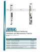
223026L2 1181113L2 DSL DSL DS1 DSX/DS1 ALM ALM ESF/ SF ESF/ SF (YEL) (GRN) (YEL) (GRN) B8ZS/AMI DSX-1 B8ZS / AMI HDSL2 (YEL) (GRN) DS1 (YEL) (GRN) LLB / RLB LBK (YEL) (GRN) TX E Q L B K RX TX LOC REM M O N RX C U S T TX M O N RX R S 2 3 2 ® HDSL2 for General Distribution Installation and Maintenance Practice Document Number: 61223HDSL2L2-5B June 2005 Part Number Description CLEI 1181113L2 Total Access 3000 H2TU-C T1L71YLA_ _ 1223001L2 220/E220 HDSL2 H2TU-C T1L722MA
HDSL2 for General Distribution Installation and Maintenance Practice Trademarks Front Matter Any brand names and product names included in this manual are trademarks, registered trademarks, or trade names of their respective holders. HiGain® is a registered trademark of ADC Telecommunications, Inc. To the Holder of the Manual The contents of this publication are current as of the date of publication. ADTRAN® reserves the right to change the contents without prior notice.
HDSL2 for General Distribution Installation and Maintenance Practice Revision History Revision Date A November 2004 B June 2005 Description of Changes Initial release Add new product: 1223004L12, 3192M H2TU-C; Edits to front panel graphics to add TScan; power descriptions; compatibility statements; appearance Conventions The following typographical conventions are used in this document: This font indicates a cross-reference link. First-time references to tables and figures are shown in this font.
HDSL2 for General Distribution Installation and Maintenance Practice Training ADTRAN offers training courses on our products. These courses include overviews on product features and functions while covering applications of ADTRAN’s product lines. ADTRAN provides a variety of training options, including customized training and courses taught at our facilities or at customer sites. For more information about training, please contact us. Training Phone: 800-615-1176, ext.
Contents Product Description. . . . . . . . . . . . . . . . . . . . . . . . . . . . . . . . . . . . . . . . . . . . . . . . . . . . . . . . . . . . . . . . . . . . . . . . Illustrations . . . . . . . . . . . . . . . . . . . . . . . . . . . . . . . . . . . . . . . . . . . . . . . . . . . . . . . . . . . . . . . . . . . . . . . . . . . . Compliance . . . . . . . . . . . . . . . . . . . . . . . . . . . . . . . . . . . . . . . . . . . . . . . . . . . . . . . . . . . . . . . . . . . . . . . . . . . .
Contents HDSL2 for General Distribution Installation and Maintenance Practice Scratch Pad, Circuit ID, Time/Date Screen . . . . . . . . . . . . . . . . . . . . . . . . . . . . . . . . . . . . . . . . . . . . . . . Terminal Modes . . . . . . . . . . . . . . . . . . . . . . . . . . . . . . . . . . . . . . . . . . . . . . . . . . . . . . . . . . . . . . . . . . . . Alarm History . . . . . . . . . . . . . . . . . . . . . . . . . . . . . . . . . . . . . . . . . . . . . . . . . . . . . . . . . . . . . . . . . .
HDSL2 for General Distribution Installation and Maintenance Practice Contents Fast Retrain Feature . . . . . . . . . . . . . . . . . . . . . . . . . . . . . . . . . . . . . . . . . . . . . . . . . . . . . . . . . . . . . . B-10 Appendix C Front Panel DSX and MUX Mode Test Access . . . . . . . . . . . . . . . . . . . . . . . . . . . . . . . . . . . . . . . . C-1 General . . . . . . . . . . . . . . . . . . . . . . . . . . . . . . . . . . . . . . . . . . . . . . . . . . . . . . . . . . . . . . . . . . . . .
Contents Figure 20. Figure 21. Figure 22. Figure 23. Figure 24. Figure 25. Figure 26. Figure 27. Figure 28. Figure 29. Figure 30. Figure 31. Figure 32. Figure 33. Figure 34. Figure 35. Figure 36. Figure 37. Figure 38. Figure 39. Figure 40. Figure 41. Figure 42. Figure 43. Figure 44. Figure 45. Figure 46. Figure 47. Figure 48. Figure 49. Figure 50. Figure 51. Figure 52. Figure 53. Figure B-1. Figure B-2. Figure B-3. Figure B-4. Figure B-5. Figure C-1. Figure C-2. Figure C-3. Figure C-4. Figure C-5.
HDSL2 for General Distribution Installation and Maintenance Practice Contents Tables Table 1. Table 2. Table 4. Table 5. Table 6. Table 7. Table 8. Table 9. Table 10. Table 11. Table 12. Table 13. Table 14. Table 15. Table 16. Table A-1. Table A-2. HDSL2 Central Office Modules . . . . . . . . . . . . . . . . . . . . . . . . . . . . . . . . . . . . . . . . . . . . . 1 HDSL2 Remote Modules . . . . . . . . . . . . . . . . . . . . . . . . . . . . . . . . . . . . . . . . . . . . . . . . . .
Contents x HDSL2 for General Distribution Installation and Maintenance Practice 61223HDSL2L2-5B
HDSL2 for General Distribution PRODUCT DESCRIPTION The HDSL2 modules referenced in this document are used to deploy a T1 circuit using 2-wire metallic facilities. HDSL2 provides extended range to DS1/T1 transport while providing spectral compatibility with ADSL and other transport technologies. The ADTRAN HDSL2 Transceiver Unit for Central Office (H2TU-C) works in conjunction with the ADTRAN HDSL2 Transceiver Remote Unit (H2TU-R) to provide a DS1 service up to 12,000 feet on the local loop.
Product Description HDSL2 for General Distribution Installation and Maintenance Practice Illustrations Figure 1 illustrates the front panels of the ADTRAN H2TU-C modules approved for general distribution.
HDSL2 for General Distribution Installation and Maintenance Practice Product Description Figure 2 illustrates the front panels of the ADTRAN H2TU-R modules approved for general distribution.
Product Description HDSL2 for General Distribution Installation and Maintenance Practice Compliance ADTRAN HDSL2 modules are NRTL listed to the applicable UL standards. The HDSL2 modules are to be installed in a restricted access location and in a type “B” or “E” enclosure only. These devices comply with Part 15 of the FCC rules. Operation is subject to the following two conditions: 1. This device may not cause harmful interference. 2.
HDSL2 for General Distribution Installation and Maintenance Practice Installation Guidelines INSTALLATION GUIDELINES C A U T I O N ! SUBJECT TO ELECTROSTATIC DAMAGE OR DECREASE IN RELIABILITY. HANDLING PRECAUTIONS REQUIRED. After unpacking an HDSL2 module, inspect it for damage. If damage has occurred, file a claim with the carrier, then contact ADTRAN Customer Service. For more information, refer to “Appendix D, Warranty”.
Installation Guidelines HDSL2 for General Distribution Installation and Maintenance Practice Powering Options H2TU-C An H2TU-C module is capable of span powering an H2TU-R module by applying current to the local loop. Current from 10 to 150 mA is coupled onto an HDSL2 span to power the H2TU-R module when required. Figure 3 shows the HDSL2 span powering diagram. SPAN CURRENT TIP (+) HDSL2 SPAN POWER 190 V RING (-) Figure 3.
HDSL2 for General Distribution Installation and Maintenance Practice Installation Guidelines 4. Slide the unit into the module slot. Simultaneous thumb pressure at the top and bottom of the unit will ensure that the module is firmly seated against the backplane of the chassis. 5. Secure the module in place by pushing in on the ejector latch. All Other Modules To install any of the HDSL2 modules, with the exception of those explained above, perform the following steps: 1.
Connections HDSL2 for General Distribution Installation and Maintenance Practice CONNECTIONS An H2TU-C module occupies one card slot in the respective Office Repeater Bay for which it is named. Power and alarm signals are provided to the module through the backplane of the shelf. DSX-1 and HDSL2 loop signals are connected to the wire-wrap pins or mass termination (amphenol) shelf connectors corresponding to the slot the module occupies.
HDSL2 for General Distribution Installation and Maintenance Practice 1 2 3 4 5 6 7 8 9 10 A B C D E F H J K L R Tx DSX (In from DSX) R1 Rx DSX (Out to DSX) GND -48 VDC R HDSL2 Loop Fuse Alarm (to Alarm Module) T Tx DSX (In from DSX) T1 Rx DSX (Out to DSX) Frame Ground T HDSL2 Loop 3192 Edge Connector Wiring 1 2 3 4 5 6 7 8 9 10 A B C D E F H J K L Connections R Tx DSX (In from DSX) R1 Rx DSX (Out to DSX) GND HMU Management Bus -48 VDC R HDSL2 Loop Fuse Alarm (to Alarm Module) T Tx DSX (In from DSX
Provisioning HDSL2 for General Distribution Installation and Maintenance Practice Total Access 3000 H2TU-C Edge Connector The Total Access 3000 shelf delivers DSX-1 from the network to the H2TU-C via connectors on the backplane labeled Pair 7 and Pair 8. The HDSL2 signal is provided toward the customer via the backplane connector labeled Pair 2. Pins 1 and 33 of the connectors Pair 7 and Pair 8 are the DSX connections for the H2TU-C in slot 1. Pins 2 and 34 of these connectors are associated with slot 2.
HDSL2 for General Distribution Installation and Maintenance Practice Provisioning Table 6. Provisioning Options Provisioning Option Option Settings Default Settings 1. DSX-1 Line Build Out 1 0-133 feet, 133-266 feet, 266-399 feet, 399-533 feet, 533-655 feet, EXTERNAL 0 to 133 feet 2. DSX-1/DS1 Line Code B8ZS, AMI B8ZS 3. DSX-1/DS1 Framing SF, ESF, Unframed, Auto ESF 4. Force Frame Conversion Disabled, Enabled Disabled 5. Smartjack Loopback Disabled, Enabled Enabled 6.
HDSL2 System Testing HDSL2 for General Distribution Installation and Maintenance Practice Provisioning Options, Total Access 3000 H2TU-C The Total Access 3000 H2TU-C is provisioned through the SCU on the Total Access 3000 chassis. In addition to the options shown in Table 6 on page 11, the options shown in Table 7 apply. Table 7. Total Access 3000 Additional Provisioning Options Provisioning Option Option Settings Default Settings 15.
HDSL2 for General Distribution Installation and Maintenance Practice HDSL2 System Testing H2TU-C Bantam Jacks The front panel of an H2TU-C module contains both metallic splitting (EQ) and monitor (MON) bantam jacks. The EQ jacks provide an intrusive access point, interrupting signal access to the local loop. This will enable the user to transmit a test signal toward an H2TU-R module and to receive a test signal from an H2TU-R module.
HDSL2 System Testing HDSL2 for General Distribution Installation and Maintenance Practice T1 DSX-1 R1 DSX-1 BRG Rx H2TUR T R EQ Rx Tx H2TU-C DATA PUMP CPE DS1 INTERFACE DS1 MON HDSL2 POWER Rx EQ Tx T1 R1 DSX-1 BRG Tx T DSX-1 R H2TU-C Bantam Jack Arrangement (except DDM+ H2TU-C) H2TU-R Bantam Jack Arrangement Figure 7. Bantam Jack Arrangements Loopbacks The ADTRAN HDSL2 modules respond to three different loopback activation processes.
HDSL2 for General Distribution Installation and Maintenance Practice HDSL2 System Testing In addition to network-side loopbacks, an H2TU-C module provides customer-side loopbacks initiated by using either the terminal control port or in-band loop codes. For more information, refer to “Appendix A, HDSL2 Loopbacks”. In this mode, an AIS signal (all ones) is supplied to the network.
H2TU-C Front Panel Operation HDSL2 for General Distribution Installation and Maintenance Practice H2TU-C FRONT PANEL OPERATION LED indicators mounted on the front panel of the unit provide status of the HDSL2 circuit. Each indicator is described in Table 9 for the H2TU-C and Table 10 for the H2TU-R. Table 9.
HDSL2 for General Distribution Installation and Maintenance Practice Control Port Operation CONTROL PORT OPERATION The H2TU-C modules provide a DB-9 connector on the front panel that supplies an RS-232 interface for connection to a controlling terminal. The pinout of the DB-9 is illustrated in Figure 9. 1 6 7 8 9 2 TXD (Transmit Data) 3 RXD (Receive Data) 4 5 SGN (Signal Ground) Figure 9.
Control Port Operation HDSL2 for General Distribution Installation and Maintenance Practice Screens The screens illustrated in Figure 10 through Figure 47 are for an HDSL2 circuit deployed with the ADTRAN HDSL2 technology. The circuit includes an H2TU-C module and an H2TU-R module. Logon to Main Menu A terminal session is initiated by entering multiple spacebar characters, which are used by an H2TU-C module to determine the speed of the terminal.
HDSL2 for General Distribution Installation and Maintenance Practice Control Port Operation Descriptions for the menu items on the HDSL2 Main Menu include the following: • “HDSL2 Unit Information” on page 21 • “Provisioning” on page 22 • “Span Status” on page 24 • “Loopbacks and Test” on page 27 • “Performance History” on page 31 • “Scratch Pad, Circuit ID, Time/Date Screen” on page 33 • “Terminal Modes” on page 34 • “Alarm History” on page 35 • “Event History” on page 38 • “System PM/Screen Report” on pa
Control Port Operation HDSL2 for General Distribution Installation and Maintenance Practice Shelf: 1 Unacknowledged Alarms: None Total Access System 03/01/05 09:29 Total Access 1. 2. 3. 4. 5. 6. 7. System Controller Common A - [.....] Common B - [.....] Access Modules System Alarms Network Management Logoff Selection: '?' - System Help Screen Figure 12. Total Access Main Menu The Access Module Menus screen (Figure 13) will display the access modules occupying the Total Access 3000 shelf.
HDSL2 for General Distribution Installation and Maintenance Practice Control Port Operation Shelf: 1 Slot: 15 Total Access System Unacknowledged Alarms: None Circuit ID: 03/01/05 09:29 HDSL2 Main Menu 1. 2. 3. 4. 5. 6. 7. 8. 9. 10. 11. 12. HDSL2 Unit Information Provisioning Status Loopbacks and Test Performance Monitoring Scratch Pad, Ckt ID Alarm History Event History System Status/PM Report Clear PM and Alarm Histories Troubleshooting Flash Upgrade Selection: Figure 14.
Control Port Operation HDSL2 for General Distribution Installation and Maintenance Practice Provisioning The Provisioning menu (Figure 16) displays current settings. To change a particular option setting (for example, “1” for DSX-1 Line Build Out) select the appropriate number, press ENTER, and the new menu will appear with a list of the available settings. To return to this screen and/or the Main Menu, press ESC.
HDSL2 for General Distribution Installation and Maintenance Practice Control Port Operation To re-deploy this unit, press D which restores the factory default settings to those shown in Table 6 and Table 7. The options shown in these tables are available with the H2TU-R (P/N 1223026L2). Some settings may differ when using different H2TU-Rs. Shelf: 1 Slot: 14 Total Access System Unacknowledged Alarms: None Circuit ID: 03/01/05 09:29 Provisioning 1. 2. 3. 4. 5. 6. 7. 8. 9. 10. 11. 12. 13. 14. 15. 16. N.
Control Port Operation HDSL2 for General Distribution Installation and Maintenance Practice Span Status The Span Status Screen (Figure 19) provides quick access to status information for each HDSL2 receiver in the circuit. Circuit ID:HNTSVLALHDSL2 Press ESC to return to previous menu 03/01/05 09:29:45 Span Status Screen ATTEN ______ <-00dB-> ______ |H2TUC | |H2TUR | --LOS->| | | |------> | | | | NET | |<--------->| | CUST | |17dB 17dB| | <------| | MARGIN | |<-LOS-DSX-1 |______| |______| DS1 1. 2.
HDSL2 for General Distribution Installation and Maintenance Practice Control Port Operation Status Screen Legend Screen The Status Screen Legend (Figure 21) provides a description of messages used on the Status screens.
Control Port Operation HDSL2 for General Distribution Installation and Maintenance Practice Total Access 3000 H2TU-C Auto In Service Status Screen The Auto In Service Status Screen (Figure 23) provides the status of the Auto In Service feature. The T1 alarm indications will display if the External Alarms option is enabled on the Provisioning menu (Figure 17). The Auto In Service Status screen also indicates the startup or exit period remaining as either 1, 4, 8, or 24 hours.
HDSL2 for General Distribution Installation and Maintenance Practice Control Port Operation Loopbacks and Test The Loopback and Test Commands screen (Figure 24) provides the user with the ability to initiate or terminate all available HDSL2 loopbacks. Each HDSL2 circuit component can be looped toward the network or customer from this screen. Unit self tests can also be initiated from this screen.
Control Port Operation HDSL2 for General Distribution Installation and Maintenance Practice Shelf: 5 Slot: 22 Total Access System Unacknowledged Alarms: None Circuit ID: Loopback and Test Commands ______ ______ |H2TU-C | |H2TU-R | ------>| | | |------> | | | | NET | |<--------->| | CUST | | | | <------| | | |<-----DSX-1 |______| |______| DS1 1. 2. 3. 4. 5. 6. 7.
HDSL2 for General Distribution Installation and Maintenance Practice Shelf: 1 Slot: 18 Total Access System Unacknowledged Alarms: None Circuit ID: BERT Test Screen Control Port Operation 03/01/05 09:29 Test Results ---------------------------------------------------Test Direction: Customer Unframed Pattern Generation: OFF Pattern: QRSS Pattern Line Coding: B8ZS Bit Errors: 0000000 Bit Error Rate: 0.
Control Port Operation HDSL2 for General Distribution Installation and Maintenance Practice Option 4, Enter Test Timeout from the BERT Test Screen displays the Timeout Screen (Figure 28). The time out can run for a specific duration by entering the hours and/or minutes, or can run indefinitely by entering 00:00, as indicated by the note on the screen.
HDSL2 for General Distribution Installation and Maintenance Practice Control Port Operation Performance History The Performance History screens (Figure 30) display the historical HDSL2 and T1 performance data in several different registers. At each 15-minute interval, the performance information is transferred to the previous 15-minute performance data register. This unit stores performance data in 15-minute increments for the last 24-hour period.
Control Port Operation HDSL2 for General Distribution Installation and Maintenance Practice Circuit ID:HNTSVLALHDSL2 Press ESC to return to previous menu 03/01/05 09:29:45 Performance Data Definitions H2TUC, H2TUR, and H2R LOOP Related: ES-L Errored Seconds SES-L Severely Errored Seconds UAS-L Unavailable Seconds HDSL2 Framing CRC>=1 or LOSW>=1 CRC>=50 or LOSW>=1 >10 cont.
HDSL2 for General Distribution Installation and Maintenance Practice Control Port Operation Scratch Pad, Circuit ID, Time/Date Screen The Scratch Pad, Circuit ID, Time/Date screen (Figure 33) provides a logging medium for circuit information. The format for the items on this screen are as follows: • The scratch pad is for circuit-specific notes and can hold 50 alphanumeric characters in any combination. • The circuit ID can be any alphanumeric string up to 25 characters in length.
Control Port Operation HDSL2 for General Distribution Installation and Maintenance Practice Terminal Modes The module used in this example includes two terminal emulation modes. • Manual Update Mode - This mode is used to manually update the screens. This mode supports efficient print screen and log file utilities for storage of key provisioning parameters, alarm or performance history and current system status. The message “3 SPACES TO UPDATE” appears at the top of each screen.
HDSL2 for General Distribution Installation and Maintenance Practice Control Port Operation Alarm History The Alarm History screens are divided into three separate screens: • “T1 Alarm History” on page 35 • “HDSL2 Span History” on page 36 • “HDSL2 Facility Alarm History” on page 37 T1 Alarm History The T1 Alarm History screen (Figure 35) displays the following information: • DSX-1/DS1 Red Alarm • DSX-1/DS1 Yellow Alarm • DSX-1/DS1 Blue Alarm Circuit ID:HNTSVLALHDSL2 Press ESC to return to previous menu
Control Port Operation HDSL2 for General Distribution Installation and Maintenance Practice HDSL2 Span History The HDSL2 Span History screen (Figure 36) displays the following information: • Loss of Sync for each HDSL2 receiver • Margin Threshold Alarm for each HDSL2 receiver • Attenuation Threshold Alarm for each HDSL2 receiver Circuit ID:HNTSVLALHDSL2 Press ESC to return to previous menu 03/01/05 09:29:45 HDSL2 Span History LOCATION ALARM FIRST LAST CURRENT COUNT -------------------------------------
HDSL2 for General Distribution Installation and Maintenance Practice Control Port Operation HDSL2 Facility Alarm History The HDSL2 Facility Alarm History screen (Figure 37) displays the following information: • DC Open • Over-current (short) • Ground fault • Power cycle Circuit ID:HNTSVLALHDSL2 Press ESC to return to previous menu 03/01/05 09:29:45 Facility Alarm History LOCATION ALARM FIRST LAST CURRENT COUNT -------------------------------------------------------------------------------FACILITY DC OP
Control Port Operation HDSL2 for General Distribution Installation and Maintenance Practice Event History The Event History screen (Figure 38) provides a log history of HDSL2 circuit events.
HDSL2 for General Distribution Installation and Maintenance Practice Control Port Operation System PM/Screen Report The System PM/Screen Report option (Figure 39) offers four types of reports on performance monitoring. Selecting a report type will display all the reports for that category on the screen at once, which is more efficient than accessing each menu individually. 6. 7. 8. 9. 10. 11. 12. 13.
Control Port Operation HDSL2 for General Distribution Installation and Maintenance Practice Troubleshooting The Troubleshooting screens include the new feature “Splice Detection.” This and other new features are described in more detail in “Appendix B, HDSL2 Features”. The Troubleshooting screen (Figure 41) provides troubleshooting menu items at the bottom of the screen plus ADTRAN contact information.
HDSL2 for General Distribution Installation and Maintenance Practice Control Port Operation Troubleshooting Guidance Selecting the option number associated with the Troubleshooting Guidance selection on the Troubleshooting screen causes an H2TU-C module to read the operational status of the circuit and return troubleshooting guidance to the probable cause of the trouble, as shown in Figure 42.
Control Port Operation HDSL2 for General Distribution Installation and Maintenance Practice General Information The General Information screen (Figure 43), from the main Troubleshooting screen, provides a summary of the deployment guidelines necessary to provision this HDSL2 circuit.
HDSL2 for General Distribution Installation and Maintenance Practice Control Port Operation Chronic Circuit Guidance Selecting the Chronic Circuit Guidance option displays the Chronic Circuit Problems screen (Figure 44). General information about circuits with bad splices is provided as well as a menu to the Bad Splice Detection feature. Splices that are varying in impedance will cause the HDSL data pump to see a reduced and/or fluctuating signal quality (margin).
Control Port Operation HDSL2 for General Distribution Installation and Maintenance Practice The (B) Back command will allow the technician to scroll back through the last 14 days Splice Detection Results.
HDSL2 for General Distribution Installation and Maintenance Practice Circuit ID: H2TUC Splice (feet) -----0000 0250 0530 0810 1090 1370 1650 1930 2210 2490 2770 3050 3330 3610 Control Port Operation 11/05/04 09:29:45 Press ESC to return to previous menu Splice Histogram Screen Press C to Change H2TUC | Splice | | H2TUC H2TUR (feet) | H2TUC H2TUR | -------------- | --------| 00 00 3890 | 00 00 | 09 00 4170 | 00 00 | 00 00 4455 | 00 00 | 00 00 4740 | 00 00 | 00 00 5025 | 00 00 | 00 00 5310 | 00 00 | 00 0
Control Port Operation HDSL2 for General Distribution Installation and Maintenance Practice Virtual Terminal Control The Virtual Terminal Control screen (Figure 47) is available on all modules except the Total Access 3000 H2TU-C. It allows control of remote unit provisioning from an H2TU-C module. Select the Log into H2TU-R option from this screen, and press ENTER to begin a user-initiated session with the remote unit. When the remote session is completed, press CTRL+X to terminate the session.
HDSL2 for General Distribution Installation and Maintenance Practice Control Port Operation Total Access 3000 H2TU-C Flash Upgrade Ability to download new firmware for the unit is available via the Total Access H2TU-C Flash Image screen (Figure 48). This feature allows the download and installation of a firmware upgrade. Any existing provisioning setting will be retained, while new provisioning items will assume the factory default settings.
Control Port Operation HDSL2 for General Distribution Installation and Maintenance Practice Shelf: 1 Slot: 14 Total Access System Unacknowledged Alarms: INFO Circuit ID:HntsvlALMn0103 03/01/05 10:59 Download H2TU-C via Y-Modem This utility programs the H2TUC. The VT100 terminal emulation program used must support Y-Modem file transfers and have access to the software binary file (*.bin). 1. 2. Start Transfer Abort Selection: Figure 49.
HDSL2 for General Distribution Installation and Maintenance Practice Control Port Operation The Download H2TUC via TFTP menu (Figure 51) is utilized to perform a TFTP file transfer from a remotely located computer/server to the H2TU-C. During TFTP transfers, the SCU continues to act as an intermediary to receive the file data from the remote computer and then send it to the H2TU-C unit.
Control Port Operation HDSL2 for General Distribution Installation and Maintenance Practice Boot Block The Boot Block Status screen (Figure 52) provides the status of the Boot Block sector, which in rare cases can become locked. If locked, the bootcode cannot be upgraded by future firmware upgrades. The bootcode is seldom changed with new download code. The bootcode is the small piece of code that allows firmware upgrades on the H4TU-C unit.
HDSL2 for General Distribution Installation and Maintenance Practice HDSL2 Deployment Guidelines HDSL2 DEPLOYMENT GUIDELINES The ADTRAN HDSL2 system is designed to provide DS1 based services over loops designed to comply with carrier service area (CSA) guidelines. CSA deployment guidelines are given below: • All loops are nonloaded only. • For loops with 26-AWG cable, the maximum loop length including bridged tap lengths is 9 kilofeet.
Maintenance HDSL2 for General Distribution Installation and Maintenance Practice Loop loss per kilofoot for standard wire gauges is summarized in Table 12. Table 12. HDSL2 Loss Values Cable Gauge Cable Type 68°F Temperature 90°F 120°F 26 PIC 3.902 4.051 4.253 26 Pulp 4.030 4.179 4.381 24 PIC 2.863 2.957 3.083 24 Pulp 3.159 3.257 3.391 22 PIC 2.198 2.255 2.333 22 Pulp 2.483 2.545 2.629 19 PIC 1.551 1.587 1.634 19 Pulp 1.817 1.856 1.
HDSL2 for General Distribution Installation and Maintenance Practice Troubleshooting TROUBLESHOOTING Table 13 provides a H2TU-C troubleshooting guide to assist in problem resolution. Table 13. H2TU-C Troubleshooting Guidelines Condition Solution All front panel indicators are off. 1. Verify that –48 VDC power is properly connected to the shelf. 2. Inspect the fuse and verify that it is not blown. 3. Insert the H2TU-C into a slot known to be in good working condition, and check the LED indicators. 4.
Troubleshooting HDSL2 for General Distribution Installation and Maintenance Practice Table 14 provides an H2TU-R troubleshooting guide to assist in problem resolution. Table 14. H2TU-R Troubleshooting Guidelines Condition Solution All front panel indicators are off. 1. Make sure the H2TU-R is properly seated in the housing. 2. Check powering voltage: • For Span Powered unit (1223026L2) verify that the H2TU-C is delivering sufficient simplex voltage to the loop.
HDSL2 for General Distribution Installation and Maintenance Practice Specifications SPECIFICATIONS Table 15 lists the product specifications for each H2TU-C included in this practice. Table 15. H2TU-C Product Specifications Specification Description Loop Interface Modulation Type: Mode: Number of Pairs: Bit Rate: Baud Rate: Service Range: Loop Loss: 16-TC PAM Full Duplex, Partially Overlapped, Echo Canceling 1 1.552 Mbps 517.
Specifications HDSL2 for General Distribution Installation and Maintenance Practice Table 15. H2TU-C Product Specifications (Continued) Specification Description Tests Diagnostics: Self-Test Local Loopback (H2TU-C) Remote Loopback (H2TU-R) Physical Dimensions: Total Access 3000 H2TU-C 5.35 in. high × 0.69 in. wide × 10.2 in. deep 220 H2TU-C: 6.00 in. high × 1.40 in. wide × 10.00 in. deep DDM+ H2TU-C: 4.00 in. high × 0.69 in. wide × 10.13 in. deep 3192 H2TU-C: 4.75 in. high × 0.69 in. wide × 10.
HDSL2 for General Distribution Installation and Maintenance Practice Specifications Table 16 lists the product specifications for each H2TU-R included in this practice. Table 16. H2TU-R Product Specifications Specification Description Loop Interface Modulation Type: Mode: Number of Pairs: Bit Rate: Baud Rate: Service Range: Loop Loss: 16-TC PAM Full Duplex, Partially Overlapped, Echo Canceling 1 1.552 Mbps 517.
Specifications HDSL2 for General Distribution Installation and Maintenance Practice Table 16. H2TU-R Product Specifications (Continued) Specification Description Tests Diagnostics: Self Test Loopback (H2TU-R) initiated with T1 NIU inband codes Loopback (H2TU-R) initiated with H2TU-C command Loopback (H2TU-R) initiated manually Loopback (H2TU-R) initiated from H2TU-R control port Physical Dimensions: T200 H2TU-R: Weight: Height: 5.50 inches Width: 0.69 inch Depth: 6.
Appendix A HDSL2 Loopbacks HDSL2 LOOPBACK AND CONTROL CODES This appendix describes the operation of the HDSL2 system in detection of inband and ESF facility data link loopback codes. Upon deactivation of a loopback, the HDSL2 system will synchronize automatically. Loopback Process Description In general, the loopback process for the HDSL2 system elements is modeled on the corresponding DS1 system process.
HDSL2 Loopback and Control Codes HDSL2 for General Distribution Installation and Maintenance Practice NOTE In all control code sequences presented, the inband codes are shown leftmost bit transmitted first, and the ESF data link codes with rightmost bit transmitted first. Table A-1.
HDSL2 for General Distribution Installation and Maintenance Practice HDSL2 Loopback and Control Codes Table A-2. In-Band Addressable Loopback Codes (All codes listed below must be sent for a minimum of 5 seconds in order for them to be detected and acted upon.) Function Code Source Code and Response Arm 11000 (2-in-5 pattern) (N) If the pattern is sent from the network, the units arm, and the H2TU-R loops back if Smartjack Loopback is enabled.
HDSL2 Loopback and Control Codes HDSL2 for General Distribution Installation and Maintenance Practice Table A-2. In-Band Addressable Loopback Codes (Continued) (All codes listed below must be sent for a minimum of 5 seconds in order for them to be detected and acted upon.) Function Code Loopback Query D5D5 (1101 0101 1101 0101) (N) If unit is in loopback towards pattern, errors are periodically injected toward pattern as long as pattern is present.
Appendix B HDSL2 Features HDSL NEW ENHANCED FEATURE OVERVIEW The new HDSL2 and HDSL4 products contain new features to enhance their performance and help the customer reduce down time.
HDSL New Enhanced Feature Overview CO C HDSL2 for General Distribution Installation and Maintenance Practice Outside Plant Facilities X R Open on either conductor R Open on both conductors C R Short between T&R C R Short to ground from either or both conductors C X X Figure B-1. TScan Diagnostic Capabilities NOTE For implementation of TScan please contact an ADTRAN sales representative. Splice Detection Feature Runtime TScan 2.
HDSL2 for General Distribution Installation and Maintenance Practice HDSL New Enhanced Feature Overview The support mechanisms for this feature can logically be divided into the following six segments: • Splice Detection Algorithm • FDL Support • Screen Support • EEPROM Support • EOC Support • Event Support These support mechanisms are described in the following subsections. Splice Detection Algorithm The splice detection algorithm is designed to detect bad splices in training mode and data mode.
HDSL New Enhanced Feature Overview HDSL2 for General Distribution Installation and Maintenance Practice EEPROM Support The results of the splice detector are stored to the Electronically Erasable Programmable Read-Only Memory (EEPROM) on a daily basis at the same time the 24-hour PM registers are stored to EEPROM. A total of 14 days splice detection history is retained. This history is read from the EEPROM upon power up.
HDSL2 for General Distribution Installation and Maintenance Practice HDSL New Enhanced Feature Overview Splices that are varying in impedance will cause the HDSL data pump to see a reduced and/or fluctuating signal quality (margin). The HDSL data pump will attempt to track these changes, but when the changes become too severe, errors or loss of synchronization result. This is reflected by the symptoms described on this screen.
HDSL New Enhanced Feature Overview HDSL2 for General Distribution Installation and Maintenance Practice Circuit ID:HNTSVLALHDSL2 Press ESC to return to previous menu 01/09/05 12:16:05 * Note: Chronic Circuit Results are only valid after all other circuit * * qualification tests have been performed and failed to show a trouble !! * Splice Detector Version 1 Result Definitions: --------------------------------------------NTF - No Trouble Found yet. LOS - Unit not in sync.
HDSL2 for General Distribution Installation and Maintenance Practice HDSL New Enhanced Feature Overview Circuit ID: H2TUC Splice (feet) -----0000 0250 0530 0810 1090 1370 1650 1930 2210 2490 2770 3050 3330 3610 11/05/04 09:29:45 Press ESC to return to previous menu Splice Histogram Screen Press C to Change H2TUC | Splice | | H2TUC H2TUR (feet) | H2TUC H2TUR | -------------- | --------| 00 00 3890 | 00 00 | 09 00 4170 | 00 00 | 00 00 4455 | 00 00 | 00 00 4740 | 00 00 | 00 00 5025 | 00 00 | 00 00 5310 |
HDSL New Enhanced Feature Overview HDSL2 for General Distribution Installation and Maintenance Practice Using the Bad Splice Detector A brief synopsis of steps that might be utilized on a trouble analysis are as follows: 1. Check the HDSL units for margin fluctuation by checking the Min & Max margins on the Detailed Span Status screen (differ by > 6 dB) corresponding to the time of the trouble. 2.
HDSL2 for General Distribution Installation and Maintenance Practice HDSL New Enhanced Feature Overview Event History Screen The Event History screen (Figure B-5) shows the messages reported in the event log due to the splice detector. Any reset of the detector is shown as well as the first detect seen since the last reset.
HDSL New Enhanced Feature Overview HDSL2 for General Distribution Installation and Maintenance Practice power. When the software detects the power fault, the data pump goes into a fault bridging mode to protect the data pump filters and to maintain service until the anomaly clears.
Appendix C Front Panel DSX and MUX Mode Test Access GENERAL Figure C-1 through Figure C-3 are DSX-1 fed modes of operation, and Figure C-4 through Figure C-7 are MUX fed modes of operation. From the Provisioning menu (“Provisioning” on page 22), the Network Source option is used to choose either MUX fed or DSX fed. When performing intrusive MUX mode testing, the equipment jack on the front panel can be configured to access the signal going to the Network or the Customer.
DSX Mode Test Access HDSL2 for General Distribution Installation and Maintenance Practice To MUX From MUX TX X RX TX DSX EQ RX To DSX From DSX 432 Ω TX DSX MON RX To CUST From CUST 432 Ω T1 BERT Figure C-1. DSX MON, Tx to Customer DSX MON, Rx from Customer The Rx of the BERT receives data from the RX MON jack (Figure C-2). This data has a monitor jack impedance of 432 ohms and comes from the customer originated data. The BERT TX is not used. This test is non-intrusive.
HDSL2 for General Distribution Installation and Maintenance Practice MUX Mode Test Access To MUX From MUX TX To DSX From DSX TX DSX EQ RX RX 432 Ω TX DSX MON RX To CUST From CUST 432 Ω T1 BERT Figure C-3. DSX EQ, Tx to Customer, Rx from Customer MUX MODE TEST ACCESS MUX Mode tests through a MUX on the Total Access 3000 shelf. MUX MON, Tx to Customer The Rx of the BERT receives data from the TX MON EQ jack (Figure C-4). This data is a copy of the data that the H2TU-C will transmit to the customer.
MUX Mode Test Access HDSL2 for General Distribution Installation and Maintenance Practice MUX MON, Rx from Customer The Rx of the BERT receives data from the RX MON jack (Figure C-5). This data is 432 ohm copy of the data that the H2TU-C will receive from the customer and route to the Total Access shelf's MUX (network). The Tx of the BERT is not used. This test is non-intrusive. To MUX From MUX TX X RX To DSX From DSX TX DSX EQ RX 432 Ω TX DSX MON RX To CUST From CUST 432 Ω T1 BERT Figure C-5.
HDSL2 for General Distribution Installation and Maintenance Practice MUX Mode Test Access MUX EQ, Tx to Customer, Rx from Customer The Tx of the BERT is connected to the EQ TX jack, and the Rx of the BERT is connected to the RX EQ jack (Figure C-7). The Tx of the BERT is then substituted for the data that the H2TU-C sends to the customer. The Rx of the BERT receives data directly from the customer. The MON TX and RX jacks are 432 ohm impedance copies of the EQ jack TX and RX. This test is intrusive.
MUX Mode Test Access HDSL2 for General Distribution Installation and Maintenance Practice This page is intentionally blank.
Appendix D Warranty WARRANTY AND CUSTOMER SERVICE ADTRAN will replace or repair this product within the warranty period if it does not meet its published specifications or fails while in service. Warranty information can be found at www.adtran.com/warranty. Refer to the following subsections for sales, support, Customer and Product Service (CAPS) requests, or further information.
® Carrier Networks Division 901 Explorer Blvd.