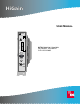
HiGain USER MANUAL HiGain HDSL2 L 1 H 2 T U • 3 8 8 H2TU-C-388 List 1 Line Unit Part Number: 150-2406-01 CLEI: VACHKW0C SETUP MODE SEL STATUS RS 232 DCE
152-388-100-02, Issue 2 Revision History of This Manual Revision Release Date Revisions Made 01 June 6, 2000 Initial release. 02 Jaunary 18, 2002 ADC rebranding Copyright Jaunary 18, 2002 © 2002 ADC DSL Systems, Inc. All rights reserved. Trademark Information ADC is a registered trademark of ADC Telecommunications, Inc. HiGain is a registered trademark of ADC DSL Systems, Inc.
152-388-100-02, Issue 2 Using This Manual USING THIS MANUAL The following conventions are used in this manual: • Monospace type indicates screen text. • Keys you press are indicated by small icons such as Y or ENTER . Key combinations to be pressed simultaneously are indicated with a plus sign as follows: CTRL + ESC . • Items you select are in bold. • Three types of messages, identified by icons, appear in text. Notes contain information about special circumstances.
Inspecting Shipment iv 152-388-100-02, Issue 2 June 6, 2000 H2TU-C-388 List 1
152-388-100-02, Issue 2 Table of Contents TABLE OF CONTENTS Overview ____________________________________________________________________________ 1 Features ..............................................................................................................................................1 Compatibility .....................................................................................................................................2 Applications ...............................................
Table of Contents 152-388-100-02, Issue 2 Testing _____________________________________________________________________________ 36 Front-Panel System Alarms............................................................................................................. 36 Alarm Option for DLC Feed ............................................................................................. 37 Retiring System Alarms ...............................................................................................
152-388-100-02, Issue 2 List of Figures LIST OF FIGURES 1. H2TU-C-388 List 1 Front Panel....................................................................................................................3 2. Installing the H2TU-C-388 into a Shelf ........................................................................................................7 3. Logon Screen.............................................................................................................................................
List of Tables 152-388-100-02, Issue 2 LIST OF TABLES 1. Front-Panel Description ................................................................................................................................ 4 2. Front-Panel Display Messages...................................................................................................................... 5 3. Navigational Keys for the HiGain Maintenance Terminal Screens............................................................ 11 4.
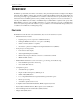
152-388-100-02, Issue 2 Overview OVERVIEW The HiGain® product family from ADC® is the industry’s first practical implementations of High- bit-rate Digital Subscriber Line 2 (HDSL2). ADC products are fully compliant with the HDSL2 standard. Providing full-rate T1 access using just a single copper pair, HDSL2 is a cost-effective solution that offers an open architecture. The open architecture inherent in HDSL2 guarantees interoperability, allowing simple and economic accommodation of network growth.
Overview 152-388-100-02, Issue 2 DS1 is used throughout this document to refer to either the remote unit’s DS1 interface or the line unit’s DSX-1 interface. COMPATIBILITY The H2TU-C-388 List 1 is designed to mount in DDM+ high-density shelves. For a list of compatible shelves see “Appendix C - Compatibility” on page 53. APPLICATIONS HiGain systems provide a cost-effective, easy-to-deploy method for delivering DS1 High Capacity Digital Service (HCDS) over a single copper pair.
152-388-100-02, Issue 2 Front Panel FRONT PANEL Figure 1 shows the H2TU-C-388 List 1 front panel. Table 1 on page 4 describes the front-panel components. For a list of front-panel display messages, refer to Table 2 on page 5. For pinout diagrams of the H2TU-C card-edge connector and craft port, refer to “Appendix A - Specifications” on page 48.
Front Panel 152-388-100-02, Issue 2 Table 1. Front-Panel Description 4 Front-Panel Feature Function Front-panel display Displays four-character status, provisioning, and alarm system messages. The front-panel display illuminates when power is initially applied. To conserve power the display only remains on for 5 minutes. Using the MODE or SEL buttons reactivates the display and restarts the 5-minute timer. Refer to Table 2 on page 5 for a listing of the four-character messages.
152-388-100-02, Issue 2 Front Panel Table 2 lists the front-panel display messages. The four-character display reports the code of an alarm, loopback, or diagnostic message and, in some cases, is followed by a second four-character message that modifies the first message with a value or current configuration setting. Table 2.
Front Panel 152-388-100-02, Issue 2 Table 2. Front-Panel Display Messages (Continued) Message Full Name Description SMJK Remote SmartJack Loopback DSX-1 signal is looped back to the network at the H2TU-R SmartJack module. DIAGNOSTIC MESSAGES A = xx Maximum Loop Attenuation The Attenuation (A) message appears followed by xx, where xx is the loop attenuation, measured in dB. ACQ Acquisition The multiplexers of the H2TU-C and H2TU-R are trying to establish synchronization over the HDSL2 loop.
2-388-100-02, Issue 2 Installation INSTALLATION Upon receipt of the equipment, inspect the contents for signs of damage. If the equipment has been damaged in transit, immediately report the extent of damage to the transportation company and to ADC. Figure 2. Installing the H2TU-C-388 into a Shelf When installing an H2TU-C in a chassis, be sure to wear an antistatic wrist strap. Avoid touching components on the circuit board.
Installation 152-388-100-02, Issue 2 VERIFICATION Once the H2TU-C-388 List 1 is installed, verify that it is operating properly. To do this, monitor the following: • Status LED • Status messages reported by the front-panel display (see Table 2 on page 5) Verification without a Downstream Device If there is no downstream device installed: 1 Verify that the H2TU-C powers up. The front-panel display illuminates and reports status messages. (See Table 2 on page 5 for a list of messages.
152-388-100-02, Issue 2 Provisioning PROVISIONING There are two provisioning methods: • • Use the MODE and SEL buttons on the front panel of the H2TU-C to: – Set system options – Reset the H2TU-C to its factory default settings for system options – Display system option settings (scroll mode) – Select system loopbacks Use a maintenance terminal (VT100 terminal or a PC running terminal emulation software) connected to the H2TU-C craft port (or to an HMU craft port) to access the HiGain HDSL2 main
Provisioning 152-388-100-02, Issue 2 Resetting to Factory Default Values All user options for the H2TU-C-388 List 1 (Table 5 on page 17) can be set to the factory default values using the MODE and SEL buttons. To set the user options to their default values: 1 Press the SEL button for 6 seconds until the following message appears: DFLT NO 2 Press the SEL button while the DFLT NO message appears.
152-388-100-02, Issue 2 5 Provisioning Configure the maintenance terminal to the following communication settings: 6 • 9600 baud • No parity • 8 data bits • 1 stop bit • Hardware flow control to OFF If necessary, press CTRL + R to refresh the HiGain HDSL2 logon screen. The Logon Screen The HiGain maintenance terminal screens allow you to monitor, provision, and troubleshoot an H2TU-C-388 List 1 system.
Provisioning 152-388-100-02, Issue 2 Menu bar Monitor Performance Event Log Config Inventory Rlogon Help +--------------------------------------------+ | | | PairGain Technologies Inc. | | HiGain Solitaire HDSL2 | | | | Voice: 800.638.0031 | | Fax : 714.832.9924 | | Web : www.pairgain.com | +--------------------------------------------+ ID: xxxx--xxxx--xxxx--xxxx Circuit ID Number 04/15/00 12:30:01 Date and Time H2TU-C System: OK Logon Device System Status Figure 3. Logon Screen Table 4.
152-388-100-02, Issue 2 Provisioning PROVISIONING TASKS After the HiGain Line Unit is successfully installed, perform these basic provisioning tasks: 1 Set the date and time (see “Setting Date and Time” on this page) 2 Set the circuit ID numbers (see “Setting Circuit ID Numbers” on page 14) 3 Make any necessary configuration changes (see “Configuring the System” on page 15) 4 Clear history, alarm, and event log screens to remove miscellaneous data during startup (see “Clearing the History, Alarm, a
Provisioning 152-388-100-02, Issue 2 Setting Circuit ID Numbers The Inventory screen provides product information on all units in the system and allows setting of the circuit and unit identification numbers. Monitor Performance Event Log Config -------------------------Product Information Unit : H2TU-C H2TU-R Product : H2TU-C-388 H2TU-R-402 List : 1 1 Sw Ver. : 2.10 2.10 Build # : 02 02 Checksum : 0x3FAE 0x3FAE H2 Xcvr : L1-RA2 1.31 L1-RA2 1.
152-388-100-02, Issue 2 Provisioning Configuring the System The Config menu (Figure 6) allows you to make the following types of system configuration changes: • Standard options (Figure 7 on page 16) • ADC options (Figure 8 on page 16) • Date and time (see “Setting Date and Time” on page 13) • Master clear (see “Clearing the History, Alarm, and Event Log Screens” on page 21) • Reset to factory default configuration (Figure 9 on page 20) Monitor Performance Event Log ID: xxxx--xxxx--xxxx--xxxx
Provisioning Monitor 152-388-100-02, Issue 2 Performance Config Inventory Rlogon Help +----------------------+ | Standard Options -> | +---------------------------------------------------+ | Loopback Timeout (LBTO) : 60 min | | Loop Attenuation Threshold (LATT) [0-40]: 35 dB | | Margin Threshold (MARG) [0-15]: 4 dB | | | DS1 Frame Formatting (FRMG) : AUTO | DS1 Line coding (DS1) : AUTO | | H2TU-C Equalization (EQL) : 0 ft | | H2TU-R Line Buildout (RLBO) : 0 dB | | Alarm Pattern (ALMP) : AIS | | H2TU-R T
152-388-100-02, Issue 2 Provisioning Table 5 describes the Standard Config screen options and lists their front-panel display codes. Table 6 on page 18 describes the ADC Config screen options. Selections in bold typeface are the factory default settings. Table 5. HiGain Line Unit List 1 Standard Config Screen Options Standard Config Screen Options Loopback Timeout Screen Display Code LBTO Selection Description NONE 20 Disables automatic time-out cancellation of all loopbacks.
Provisioning 152-388-100-02, Issue 2 Table 5. HiGain Line Unit List 1 Standard Config Screen Options (Continued) Screen Display Code Selection Description H2TU-R TLOS Loopback TLOS ENA Enables a logic loopback at the H2TU-R when an LOS occurs at its DS1 input. See Figure 25 on page 38 for LOS/AIS response priorities. Network Loopback Pattern NLBP DIS AIS Disables TLOS logic loopback. Enables the H2TU-R to transmit AIS towards the CI for any network loopback.
152-388-100-02, Issue 2 Provisioning Table 6. HiGain Line Unit List 1 ADC Config Screen Options (Continued) ADC Config Screen Options Screen Display Code Selection Description Remote Disconnect Alarm RDA ENA Enables a remote DS1 LOS condition at the input to the H2TU-R to generate an LOS alarm. AIS or LOS (depending on ALMP) is sent towards the network. DIS Prevents a remote DS1 LOS condition at the input to the H2TU-R from causing an LOS alarm.
Provisioning 152-388-100-02, Issue 2 DS1 BER (DBER) Option. The DS1 BER alarm occurs when any of the DS1 or DSX-1 performance monitoring parameters listed in Table 7 exceed the counts shown for the 24-hour period between 12:00:00 AM through 11:59:59 PM. These thresholds correspond to a 10-6 BER. All PM counters clear to zero at 12:00:00 AM or when Master Clear is selected. Table 7.
152-388-100-02, Issue 2 Provisioning Clearing the History, Alarm, and Event Log Screens Clear the History, Alarm and Event Log screens after the system has been installed and is functioning properly. This removes miscellaneous data acquired during the startup session and ensures collection of accurate and meaningful data thereafter.
Monitoring System Activity and Performance 152-388-100-02, Issue 2 MONITORING SYSTEM ACTIVITY AND PERFORMANCE The H2TU-C-388 List 1 provides two sets of maintenance screens for monitoring system activity and assessing performance. • The Monitor screens provide a graphical representation of circuit activity and allow initiation of loopbacks. • The Performance screens provide current, 25-hour, 48-hour, and 31-day performance histories and a continuous alarm history.
152-388-100-02, Issue 2 3 Monitoring System Activity and Performance To initiate a loopdown of all active loopbacks, press the SPACEBAR to select LPDN, then press ENTER or N . When prompted with the message: Are you sure (Y/N)?, press Y to initiate the loopdown or N to cancel. Table 8. Monitor Screen Descriptions Field Description Active Loopback An active loopback is indicated on the lower third of the Monitor screen. Available loopbacks are indicated by gray text.
Monitoring System Activity and Performance 152-388-100-02, Issue 2 USING THE PERFORMANCE SCREENS TO VIEW PERFORMANCE DATA The Performance screens display: • CRC statistics for the HDSL2 or DS1 interface in 31-day, 48-hour, 25-hour, and current history reports • Alarm statistics for the HDSL2 (Figure 23 on page 33) or DS1 interfaces (Figure 22 on page 31) on a continuous basis To access the Performance history screens: 1 Type 2 Press the SPACEBAR to select either interface (H2TU-C DS1, H2TU-R DS1, H
152-388-100-02, Issue 2 Monitor Monitoring System Activity and Performance Performance Event Log Config Inventory Rlogon Help H2TU-R DS-1 48 Hour History (Page 1 of 4) -----------------------------------------------------------------------------Time CV-L ES-L SES-L UAS-L CV-P ES-P SES-P UAS-P PRM-NE PRM-FE 23:00 1:00 2:00 3:00 4:00 5:00 6:00 7:00 8:00 9:00 10:00 11:00 14 10 10 12 10 10 0 0 0 0 12:00 0 0 0 2 0 0 0 0 0 0 Press: (N)ext Page, (P)revious Page, C(l)ear History ---------------------------
Monitoring System Activity and Performance 152-388-100-02, Issue 2 Examples of current statistics screens are shown below. Figure 15 and Figure 16 show statistics for the DS1 interface at the remote unit and line unit, respectively. These screens report 1-day, 1-hour, and 15-minute statistics.
152-388-100-02, Issue 2 Monitoring System Activity and Performance Table 9. Error Acronym Acronyms Used on the DS1 Performance History Screens Error Acronym Description Description CV-L Code Violation - Line Total BPV count. SES-P Severely Errored Seconds - Path Seconds with SES or CRC(ESF) ≥320 or FE (a)(SF) ≥8 (FT + FS). ES-L (b) Errored Seconds - Line Seconds with BPV ≥1. UAS-P Unavailable Seconds - Path A second of unavailability based on SES-P or AIS ≥1.
Monitoring System Activity and Performance 152-388-100-02, Issue 2 Performance History at the HDSL2 Interface The HDSL2 interface has 31-day, 48-hour, 25-hour, and current statistic screens for the H2TU-C. Figure 17 and Figure 18 below are examples of 31-day and 48-hour performance history screens. Figure 19 and Figure 20 on page 29 are examples of 25-hour and current statistics performance history screens, respectively.
152-388-100-02, Issue 2 Monitor Monitoring System Activity and Performance Event Log Performance Config Inventory Rlogon Help H2TU-C HDSL2 25 Hour History (Page 1 of 9) -----------------------------------------------------------------------------Time ES SES UAS CV LOSWS 9:45 10:00 10:15 10:30 10:45 11:00 11:15 11:30 11:45 12:00 12:15 14 10 10 12 10 12:30 0 0 0 0 0 12:45 0 0 0 2 0 Press: (N)ext Page, (P)revious Page, C(l)ear History -------------------------------------------------------------------
Monitoring System Activity and Performance Table 10.
152-388-100-02, Issue 2 Monitoring System Activity and Performance Alarm History at the DS1 Interface The Alarm History screen reports DS1 statistics for the H2TU-C (Figure 21) and the H2TU-R (Figure 22 on page 31) on a continuous basis. The types of alarms reported are described in Table 11 on page 32. Current alarms are shown in reverse video.
Monitoring System Activity and Performance 152-388-100-02, Issue 2 Table 11. Screen Alarm DS1 Alarm Descriptions Front-Panel Alarm Description H2TU-C DS1 ALARMS (Figure 21 on page 31) LLOS (a) LAIS (a) LLOS LAIS DBER DBER LOF LOF Local Loss of Signal—Loss of the H2TU-C DSX-1 input signal. Local Alarm Indication Signal—Indicates an AIS (all ones) pattern is transmitted from the local DS1 output port. The ALMP option determines whether AIS (default) or LOS is sent towards the CPE.
152-388-100-02, Issue 2 Monitoring System Activity and Performance Alarm History at the HDSL2 Interface Figure 23 shows the H2TU-C HDSL2 alarm history, and Table 12 describes the alarms.
Monitoring System Activity and Performance 152-388-100-02, Issue 2 USING THE EVENT LOG TO TRACK SYSTEM EVENTS To view a running log of system events, press E to select the Event Log. The Event Log displays the date and time of the 100 most recent events (most recent displayed first) and provides a description of each event. Refer to Table 13 on page 35 for a complete list of event log messages. • Press N or • Press T to return to the top of the log. • Press L to clear the event log.
152-388-100-02, Issue 2 Monitoring System Activity and Performance Table 13.
Testing 152-388-100-02, Issue 2 TESTING This section provides information about front-panel system alarms, LOS and AIS response, OCT55 test procedure, and loopback testing. FRONT-PANEL SYSTEM ALARMS Table 14 summarizes all possible HiGain system alarms in order of priority as they appear on the front panel. When multiple alarms occur, the front-panel display only reports the highest priority alarm. The alarm history screens display alarms also, but provide greater detail.
152-388-100-02, Issue 2 Testing Table 14. Front-Panel System Alarms Summary (Continued) Front-Panel Message (a) Alarm Description To Inhibit LOF Loss of Frame The DS1 input does not contain the ESF or SF frame pattern setting of the FRMG option. Change FRMG option to AUTO or UNFR. PRMF Performance Report Messaging - Far End Indicates H2TU-R PRM-FE BER threshold is exceeded. Set DBER threshold to DIS.
Testing 152-388-100-02, Issue 2 Remote LOS and AIS Response Figure 25 shows the different ways the H2TU-R can respond to the network, depending on the configuration of the TLOS, NLBP, RDA, and ALMP configuration options described in Table 5 on page 17 and Table 6 on page 18. Figure 25. H2TU-R LOS and AIS Response Priorities OCT55 TEST PATTERN WITH AMI LINE CODE The OCT55 test pattern can be used in unframed mode to stress the system and verify data integrity.
152-388-100-02, Issue 2 Testing LOOPBACK OPERATION HiGain has a family of loopback options for analyzing circuit functionality. The loopback signal is transmitted and returned to the sending device for comparison. This allows you to verify the integrity of the HDSL2 channels to the H2TU-C, the H2TU-C DSX-1 interface, and the DS1 channels to the customer.
Testing 152-388-100-02, Issue 2 Table 15. Summary of HiGain Loopback Codes and Activation Methods Method of Activation Loopback Code Description Test Set Craft Port MODE/SEL NLOC 1111000 4-in-7 DSX-1 signal is looped back to the network at the H2TU-C. X X X NREM 1110000 3-in-7 DSX-1 signal is looped back to the network at the H2TU-R. X X X CLOC 1111100 5-in-7 Signal from the customer is looped back to the customer at the H2TU-R.
152-388-100-02, Issue 2 Testing Special Loopback Commands In addition to the GNLB loopback command mode, a HiGain system can be configured for one of five special loopback command modes. These are selected from the maintenance terminal System Settings screen (see Table 5 on page 17) or by using the MODE and SEL buttons (see Figure 27 on page 44).
Testing 152-388-100-02, Issue 2 Manual Loopback Session A manual loopback session allows you to select any one of the HiGain loopbacks listed in Table 15 on page 40 with the exception of SmartJack loopbacks, which can only be issued by inband commands. Setting the Loopback Time-out Option Before initiating a loopback session, verify that the Loopback Time-out parameter is set to the desired setting. 1 Use the MODE and SEL buttons as described in “Setting Options through MODE and SEL” on page 9.
152-388-100-02, Issue 2 4 Testing Press SEL to activate the selected loopback. The previous loopback is terminated. Once a loopback is selected and activated, the loopback stays active until it times out (based on the LBTO setting). When a loopback times out, the display then returns to the normal display mode. You can terminate loopbacks manually and exit the MAN LPBK mode by simultaneously pressing the MODE and SEL buttons for 3 or more seconds.
Testing 152-388-100-02, Issue 2 4 Have the CO tester send the NLOC (4-in-7) inband loopup for 5 seconds. You should be able to observe the NLOC message on the front-panel display. (The Status LED on the front panel should be yellow, and the loopback mode should also be identified on the Span Status screen.) 5 Repeat Step 2. If the test passes, the problem is in the downstream direction. If it fails, the problem is in the upstream direction. Figure 27.
152-388-100-02, Issue 2 Testing A1LB, A2LB, and A5LB Test Procedures Using the codes listed in Table 16, a network tester can activate NLOC, NRG or NREM loopbacks (or SMJK, if enabled). A tester at the customer premises can activate CLOC, CRG, or CREM loopbacks. All loopbacks shown in Table 16 can also be initiated from the H2TU-C-388 front-panel MODE and SEL buttons (see “Setting Options through MODE and SEL” on page 9). Table 16.
Testing 4 152-388-100-02, Issue 2 Once armed, the H2TU-C-388 can be looped back by sending Intelligent Office Repeater (IOR) LPBK activation code 1101-0011-1101-0011 (D3D3) for at least 5 seconds.
152-388-100-02, Issue 2 Testing A3LB and A4LB Test Procedures The H2TU-C-388 can be looped back by sending the Addressable Office Repeater (AOR) LPBK activation code 1111-1111-0001-1110 (FF1E) for at least 5 seconds. This causes the H2TU-C-388 to enter the NLOC state. The Loopback Time-out setting (see “Setting the Loopback Time-out Option” on page 42) determines the duration of this loopback unless it is overridden by the reception of a second identical 16-bit loopup command before the timer expires.
Appendix A - Specifications 152-388-100-02, Issue 2 APPENDIX A - SPECIFICATIONS Power Line Voltage 0, -185 Vdc CO Supply -48 Vdc nominal (-42.5 Vdc to -56.5 Vdc) (See “Power Consumption” and “Maximum Power Dissipation” and “Maximum Current Drain” on page 49.) Electrical Protection Secondary surge and power cross protection on HDSL2 ports. Requires external primary protection.
152-388-100-02, Issue 2 Appendix A - Specifications POWER CONSUMPTION The maximum power consumption and heat dissipation depends upon the type of remote units in the system and the CPE power setting. The three most important power parameters of an H2TU-C are its maximum power consumption, its maximum power dissipation and its maximum current drain. Table 18 describes line-powered circuits on 9 kft, 26 AWG loops. Table 18.
Appendix A - Specifications 152-388-100-02, Issue 2 LOOP ATTENUATION Each loop has no more than 35 dB of loss at 196 kHz, with driving and terminating impedances of 135Ω (see Table 19 below). Table 19. HDSL2 Cable Attenuation Chart Cable Gauge Loss at 196 kHz (dB/kft) Ω per kft 26/0.4 mm 3.88 83 24/0.51 mm 2.84 52 22/0.61 mm 2.18 32 19/0.91 mm 1.54 16 HIGAIN LINE UNIT CARD-EDGE CONNECTOR Figure 28 shows the card-edge connectors on the HiGain Line Unit.
152-388-100-02, Issue 2 Appendix A - Specifications Fuse Alarm Pin 117 on the card-edge connector is a fuse alarm that is driven to -48 Vdc through a diode whenever its onboard fuse opens. CRAFT PORT Figure 29 shows the craft port adapter and its connection to a DB-9 or DB-25 connector on a maintenance terminal. Figure 29.
Appendix B - Functional Operation 152-388-100-02, Issue 2 APPENDIX B - FUNCTIONAL OPERATION ADC HDSL2 technology provides full-duplex services at standard DS1 rates over copper wires between an H2TU-C and an H2TU-R, which comprise one HiGain system. HiGain systems use ADC Overlapped PAM Transmission with Interlocking Spectra (OPTIS) transceiver systems to establish full-duplex, 1.552 kbps data channels between the H2TU-C-388 List 1 and a remotely located H2TU-R.
152-388-100-02, Issue 2 Appendix C - Compatibility APPENDIX C - COMPATIBILITY The HiGain system uses HDSL2 transmission technology as recommended by ANSI committee in compliance with the August 1999 T1-E1.4/99-006R5 HDSL2 standards. The H2TU-C-388 List 1 is compatible with the following DDM+ high-density shelves and associated equipment: • HCS-402, two-slot shelf with #150-1193-01 adapter • Shelf (23-inch) • – Larus FT2 1188 (28-slot, connectorized) – AT&T DS1 Ext.
Appendix D - Product Support 152-388-100-02, Issue 2 APPENDIX D - PRODUCT SUPPORT ADC Customer Service Group provides expert pre-sales and post-sales support and training for all its products. Technical support is available 24 hours a day, 7 days a week by contacting the ADC Technical Assistance Center (TAC). Sales Assistance 800.366.3891 extension 73000 (USA and Canada) 952.917.3000 Fax: 952.917.
152-388-100-02, Issue 2 Appendix E - Abbreviations APPENDIX E - ABBREVIATIONS HDSL2: High-bit-rate Digital Subscriber Line 2 HMS: HiGain Management Shelf HMU: HiGain Management Unit A ACO: AIS: ALM: AMI: AWG: Alarm Cutoff Alarm Indication Signal Alarm Alternate Mark Inversion American Wire Gauge I B B8ZS: Bipolar with 8-Zero Substitution B8ZSS: B8ZS Monitored Seconds BER: Bit Error Rate BPV: Bipolar Violation BPVT: Bipolar Violation Transparency C CI: CLEI: CLOC: CO: CPE: CRC: CREM: CSA: CV: Custome
Appendix E - Abbreviations SES-P: SF: SMJK: SPLB: 152-388-100-02, Issue 2 Severely Errored Seconds - Path SuperFrame SmarkJack Special Loopback T TLOS: Transmit Loss of Signal U UAS: 56 Unavailable Seconds June 6, 2000 H2TU-C-388 List 1
CERTIFICATION AND WARRANTY FCC CLASS A COMPLIANCE This equipment has been tested and found to comply with the limits for a Class A digital device, pursuant to Part 15 of the FCC Rules. These limits are designed to provide reasonable protection against harmful interference when the equipment is operated in a commercial environment.
ADC DSL Systems, Inc. 14402 Franklin Avenue Tustin, CA 92780-7013 Tel: 714.832.9922 Fax: 714.832.9924 Technical Assistance Tel: 800.638.0031 Tel: 714.730.3222 Fax: 714.730.2400 ISO 9001/TL 9000 DOCUMENT: 152-388-100-02, ISSUE 2 ´,.G¶1:¨ DNV Certification, Inc.